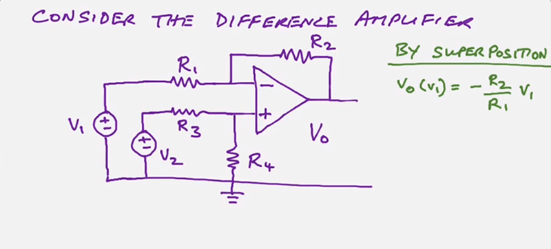
If you’ve ever wondered why an op amp has the little plus and minus symbols on it, its because at the heart of it, the device is a differential amplifier. The problem is that — ideally, at least — it has infinite gain so it works like a comparator and that’s not what you usually want. So we put resistors around the thing to constrain it and get useful amplification out of it. [Stephen Mendes] does the analysis for you about how the standard configuration for a differential amplifier works. He assumes you know the stock formulae for the inverting and non-inverting amplifier configurations and uses superposition.
[Stephen] mentions that’s the easiest way to do it and then goes on to do it sort of how we would do it as a check. We think that’s the easier method, but maybe its a matter of preference. Either way, you get the right answer.
With superposition, you basically ignore one input at a time. This reduces the circuit into an inverting amplifier when you short one power source to ground and a non-inverting when you short the other one. Superposition tells you that the real answer is the sum of those two answers.
The other way — we hate to call it the easier way — is to remember two simplifying assumptions about op amps. First, assume the op amp will do whatever it can do to make the plus and minus terminals have the same voltage. Next, assume the inputs are totally open which, for today’s op amps, isn’t too far from the truth.
Based on that, it is easy to see that V2 is divided by the voltage divider of R3 and R4. So you know the plus voltage. By our assumptions, then, you know the minus voltage too, because it should be the same. If you know that voltage and R1 you can compute the current through R1. Because the op amp terminals are open circuit (or, at least, we are pretending they are) you know the current through R1 must also be the current through R2. So we know the voltage across R2 which leads to knowing the voltage at Vo.
Let’s try a numeric version of that. Say V1=5 and V2=8. R1 and R3=10K and R2 and R4 are 20K.
- Vplus is 8V times R4/(R3+R4) or 5.3V
- That means Vminus is also 5.3V
- The current through R1 must be (5.3-5)/10000 = 33.3 microamps (sign depending on which way you consider it flowing)
- The current through R2, then must be the same, so 33.3 microamps
- To get that current through R2 with 5.3 V on one side, you need to solve .0000333 = (Vo-5.3)/20000
- If you carry enough digits, that’s 6V; if you rounded like I did you get 5.966V which is close enough
If you write out the math like [Stephen] does you’ll see the gain is 2 and since the difference in voltage is 3V, a 6V output makes perfect sense. Of course, assumptions are only good to a point. An op amp with +/-15V on the rails can’t produce 50V to wrestle the input to a particular value. But for common sense applications, those assumptions will take you a long way.
Is it easier one way or the other? We can’t say. But superposition is an important concept in its own right and can often tame an otherwise intractable circuit so even if you think it is harder to do it that way in this particular case, it is still worthwhile to follow the math.


Wow. I took one look at that schematic and thought that must be the hardest place to start explaining op-amps.
Then I googled around and found that this is common.
If you don’t believe me then calculate the load impedance on V1.
A very useful circuit primitive and ever more practical these days for the minimalist. You can now get a couple of compensated opamps in one SOT like package so with minimal resistors make a 100Meg Ohm input impedance instrumentation diff amp that runs off the smell of a fossil fuel rag. Worth looking through the oldie National Semiconductor opamp application notes from 35 years ago, most of which applicable today and with a few twerks can do math preprocessing on analogue signals before a minimal processor at suitably very low cost needs to do its thing.
Can also use opamps as good buffering for CPU a to d front ends with static protection. Thanks for post good refresher :-)
I believe that the 2 assumptions are sometimes referred to as the “Golden Rules of OP-Amps”. I think I saw them the first time in the book Art of Electronics. Just keep in mind that the first rule is only valid when there is a negative feedback loop.
I don’t think so.
The act of going into saturation on the output is by itself an attempt to get both inputs at same level, just supply voltage being the limiting factor.
If you want a thorough overview of op-amps, the TI Handbook of Operational Amplifier Applications. is a wonderful resource! 94 pages of analysis and applications.
http://www.ti.com/lit/an/sboa092b/sboa092b.pdf
The memory rule for a differential amplifier is a children’s playground seesaw.
The seesaw plank is as long as the resistors are large on either side of the axle, and the pivot is at the voltage of the positive input.
This mechanical analog gives you instant understanding of how the thing will behave.
Funny thing seeing this! I am still a freshman studying EE, but I studied this two chapters ago. For op-amps, especially modern ones, the “golden rules of op-amps” work really well. To demonstrate this, my teacher worked through the first order model for an LM709 and compared it to the result from using the ideal model, and even with such an old op-amp the error was well under 1%.
Now, go and grab the modern op-amp and design a circuit that amplifies a 100 microvolt signal to 1 Volts so your Arduino’s A/D converter can measure it.
Guess what happens? Two possibilities: your op-amp either saturates to the positive/negative rail, or produces some wild voltage in between? Why? Because there’s something between +-3 milliVolts of input offset at the inputs, and your 1:10000 amplifier tries to turn that into plus or minus 30 volts, or something in between.
Point being that if you grab an actual LM709, the first order model fails to appreciate the fact that the transistors and resistors in the chip weren’t manufactured perfectly – which is why it’s more common for older op-amps to have extra pins for balancing inputs so you can tweak the input offset.
Modern chips are laser trimmed, but you still have to pay good money to actually have an offset below 100 µV. This is annoying, because all the really interesting signals tend to be very very weak.
“Modern” op-amps really are very good now, some basic specs – \
Low offset voltage: 5 μV maximum
Extremely low offset voltage drift: 22 nV/°C maximum
Low voltage noise density:
5.8 nV/√Hz typical
117 nV p-p typical from 0.1 Hz to 10 Hz
Low input bias current: 50 pA typical
Unity-gain crossover: 3 MHz typical
Single-supply operation: input voltage range includes ground and rail-to-rail output
Wide range of operating voltages
Single-supply operation: 4.5 V to 55 V
Dual-supply operation: ±2.25 V to ±27.5 V
Integrated EMI filters
Unity-gain stable
And don’t forget instrumentation amps:
https://hackaday.com/2016/03/18/beyond-measure-instrumentation-amplifiers/
https://hackaday.com/2015/03/16/instrumentation-amplifiers-and-how-to-measure-miniscule-change/
+1
Good Links, thanks