Building an electric motor isn’t hard or technically challenging, but these motors have very little in the way of control. A stepper motor is usually employed in applications that need precision, but adding this feature to a motor adds complexity and therefore cost. There is a small $3 stepper motor available, but the downside to this motor is that it’s not exactly the Cadillac of motors, nor was it intended to be. With some coaxing, though, [T-Kuhn] was able to get a lot out of this small, cheap motor.
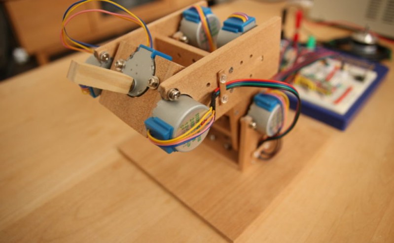
To test out the motors, [T-Kuhn] built a small robotic arm. He began by programming his own pulse generating algorithm that mimics a sine wave in order to smooth out the movement of the motor. An Arduino isn’t fast enough to do these computations, though, so he upgraded to using the ESP32. He also was able to implement the inverse kinematics on his own. The result of all this work for a specific platform and motor type is a robotic arm that has a very low cost but delivers performance of much more expensive hardware.
The robot arm was built by [T-Kuhn] too, and all of the details on that build, as well as all the schematics and code, are available on the project site if you need a low-cost robot arm or a good stepper motor controller for a low cost. There are many other ways of getting the most out of other types of low-cost motors as well.


“An Arduino isn’t fast enough to do these computations” Well, maybe not if you do sine/cosine calculations on the fly. I’ve been using a stepper motor to drive my diy turtable record player since 2004. That one uses a attiny2313 @4MHz and a lookup table of pre-calculated values to drive the motor through d/a converters and an audio amp ic. But again, the esp8266 wasn’t available in 2004 and a attiny2313 cost about the same today as the esp…
You can get very smooth movement, but the trade off is that you loose a lot of torque.
*lose* NOT *loose*
Perhaps, but loose would be correct if the record flew off. :)
I’d imagine that you need to store a lower number of precalculated values for a turntable than for a generic actuator, though, or do you have a fancy smooth acceleration/deceleration algorithm?
Having a reasonable number of samples, the key is in “playing” them at the right speed.
If you wanna get fancy you can have asymmetrically spaced sampling to increase resolution at steeper slopes.
I agree, and it is simpler than you think: First you devide a circle into 8 pieces, they can be allocated by symmetry rules. the actual 8th part can be devided asymmetrically and fitted with a polynomial of 2nd or 3rd order. You might still run into floating point equations.
Int sine ()
{
Static int x=4095, y;
x += y>> 6; y -= x>>6;
return x;
}
Pretty reasonable sine and no float….
I’m fairly sure that would give you a compiler error…
Don Lancaster created some interesting material many years ago on something he called “magic sinewaves”. This was a time when micro-controllers were expensive and limited in resources. Might be worth a look: https://www.tinaja.com/glib/msintro1.pdf
I was writing a comment on Lancaster’s work when I saw yours. Short of looking through the code for this stepper project, some more info on how sine functions are used with the motors would be nice.
If you have a decent number of samples, and interpolate between the two closest samples for your point, you can get good performance no matter what your actual application is.
I was able to create good-sounding sine waves out of a speaker, at any frequency within human hearing range, with an ATTiny4313A using a table of (if I remember right) 256 steps plus interpolation between the steps.
So your basically bitbanging microstepping? Have any documentation on this little hack?
Sorry, this was a long time ago. I’ve actually lost all the C code also. Been trying to find it for years as I want to replace the motor without rewriting all the code. I do remember filtering the output of the d/a:s with rc filters. I suspect I was using a rather limited number of values/samples and needed some interpolation…
Great project! Motor control is fascinating.
I’m a bit confused though. Are we talking about sine that you need to generate the curves to drive the windings to achieve micro-stepping, or are we talking sine that you use to compensate for inertia and make motion smooth? Because if it’s the first, I’m not sure how A4988 drivers figure in, as far as I know they manage all currents in hardware and you just send them commands. If it’s the second ok, though a sine with decent resolution can be put in a LUT.
A few years ago I experimented a bit with a BLDC made for gimbals, which are also pretty cheap. Using SVPWM control they can provide exceptionally smooth movement, but you need to add some kind of encoder for feedback, which makes things more complex. I used stm32f103 for these experiments, it is fast enough and provides enough hardware PWM channels with deadzones, which makes it ideal for such applications.
Going slow: https://www.youtube.com/watch?v=-cG3ZiQVAG0
Going fast (with PID control loop): https://www.youtube.com/watch?v=7iu8XDf4AGc
And in case anybody wants a visual–musical explanation of SVPWM, here is that: https://www.reddit.com/r/electronics/comments/28g1fq/i_just_finished_my_engineering_studies_and_this/
He’s just calculating the acceleration/deceleration profile. The stepper driver handles the microstepping current output to the motor.
All of the 3dprinter/CNC firmwares do some sort of acceleration profile. Many of them run on atmega328/Arduino Uno microcontrollers. I use grbl myself. Need to test this version to see if it is any better. Alot of work has gone into printer firmwares to make them operate as smoothly as they do.
It’s weird to use sines for that? If anything it should be something like ease-in-out speed curves and they all are easy to approximate using piecewise linear approximation.
I haven’t read the code but maybe he’s trying to do what is referred to as S curve acceleration profile.
Why does he use two motors for every joint?
Increased torque and probabilistic error smoothing, I would assume?
Also:
With a single motor you get a lot of slop in the bearing.
With 2 bearings (with some distance between them) the mechanical build is a lot sturdier.
Remember that these geared stepper motors cost around EUR 2 from Ali / Ebay / China.
The gears also have quite some backlash. So in stead of simply turning both motors do drive the axle in the same direction, you could also use them against each other to generate some kind of pre-tension in the gear to compensatte for the backlash.
I am actually thinking of doing this myself, with a stepper motor for positioning and a DC motor as a “torque generator”
*bushing*
There’s no way that there’s an actual ball bearing in there :D
That’s still a bearing. “Bearing” doesn’t imply ball bearing. An axle rotating in a block of wood is still a bearing! Just a crummy one.
looks like more torque and rigidity. They’re very cheap motors and the shaft is small enough that it can’t really be used for that large of an overhang, plus with wood coupling it would be hard to not end up with wobbly holes if only one was used per joint.
I would be curious to see this technique applied on pcb motos
I meant *motors*
The notable thing about this build is that he implemented inverse kinematics for smooth and coordinated motion.
You absolutely could implement the same with any type of motor, but good luck having enough torque or gearing with a pcb motor! These cheap steppers were chosen because steppers have high holding torque with low current, and because they have a very high gear ratio. This is why he’s able to trust the motors to not skip steps and get away with openloop control.
Can anyone explain the reason for a sine profile for velocity? A sine starts out rather abruptly. In fact, the slope of the sine is the cosine, and the cosine of zero is 1, which = full speed. So you start at full speed, go to zero and end at full speed the other direction? Or maybe this is stated wrong and the goal is a sine profile for acceleration?
My guess is the max velocity at the start is to overcome the static friction, afterwards once in motion you only have to contend with kinetic friction which will be less, and for the end of motion the deceleration force must be to smoothly bring the actuation to a stop without being choppy/sudden.
I think I’m reading it wrong. If the velocity profile is a sine, then it is max acceleration (torque) at beginning and end.
You want to start and stop slowly, or you’ll have shakes due to mass, or even missed steps.
Not sure if I understand the argument about sine starting abruptly. Sine is periodic and defined on R. The value can also be offset, if you take 1.0-abs(sin(t)), t=[0..pi/2] it would make a smooth acceleration/deceleration curve.
Really cool project though. It moves beautifully and the mod to the motor is a great hack.
Huh – his blog won’t let me comment…
FYI: a “double” on an AVR Arduino is the same size as a “float” (32bits) (This is permitted by the way C specifies variable sizes like “a double has at least as many bits as a float”, and of course it’s done because of the limitations in performance and memory size.)
(ARM-based Arduinos like the Zero have a 64-bit “double.”)
(Other than that – nice work!)
The real star here is the information that one can convert those steppers from uni- to bipolar!
Isn’t this what Trinamic drivers do?