Etch Your Own Circuit Boards In Your Kitchen

Right now, you can design a PCB, send it off to a PCB fab, and get professional finished boards in a few days for less than a dollar per square inch. This is fantastic, and it’s the driving force behind ever-dropping costs of hardware development. That’s great and all, but you can make circuit boards at home, easily, and without involving too many toxic chemicals. That’s exactly what [videoschmideo] did, and the results are pretty good.

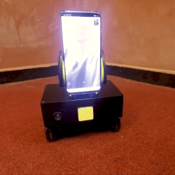
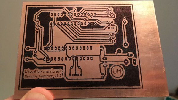
The process starts with a single-sided copper clad board that would be readily obtainable at Radio Shack if there were any of those around anymore. Once the circuit is designed, the traces and pads are printed (mirrored) out onto sticker backing paper. The toner from your laser printer is transferred to the copper with a clothes iron.

The tricky part about creating a PCB is taking away all the copper you don’t want, and for this tutorial [videoschmideo] is using a vinegar and hydrogen peroxide process. If you’re using stuff you can buy at the grocery store, you’re only getting 3% acetic acid and 3% peroxide, but given enough time and enough peroxide, it’ll do the job. After the board is etched, [videoschmideo] neutralizes the copper acetate produced with aluminum foil. The end product isn’t the safest thing in the world, but aluminum salts are much more environmentally friendly than copper compounds.

Making PCBs at home isn’t anything new, but it’s nice to be reminded that you can do so even with minimal effort and chemicals that you could rinse your mouth with. Once you do, though, you’ll probably have to drill some holes in the board. Yes, you could use a dremel, but a nice small drill press is a pleasure, and well worth the investment.

Analog Clock Goes Digital, Or Vice Versa

Designing a good clock takes a lot of considerations. It’s not just hands, faces, and numbers anymore; there are also word clocks, electronic clocks, marble clocks, or water clocks, and just about anything else imaginable can be used to tell time. Of course, electronic clocks are great for their versatility, and this one shows off an analog-looking clock that is (of course) digital, leveraging all of the perks of analog with all of the upsides of digital electronics.

One of the key design considerations that [Sasa] had while building this piece was that it needed to be silent. LEDs certainly fit that description, so the decision was made to go with an WS2812b ring. It runs using a STM ST32F103 Nucleo board (and a cheaper version of it in later versions of this clock) which shows a red LED for the current hour, yellow LEDs for the traditional analog clock divisions, a green LED for the current minute, and glows the rest of the LEDs up to the current minute with a rainbow pattern.

This is a really clean, simple build with good design at its core, and would be easy to replicate if you’re looking for an eye-catching clock to build. As a bonus, all of the schematics and code are available on the project site, so everything you need is there. If you’re looking for more inspiration, there are some clocks that are even more unique, like this marble clock that is a work of art — but is anything but silent.

Expanding 3D Printer Bed Stays True Under Fire

It’s hard to pass up another lesson in good machine design brought to us by [Mark Rehorst]. This time, [Mark] combats the relentless forces of bed deformation due to thermal expansion.

Did you think your printer stayed the same size when it heated up? Well, think again! According to [Mark’s] calculations, when heated, the bed can expand by as much as half a millimeter in the x/y direction. While x/y deformation seems like something we can ignore, that’s not always true. If our bed is rigidly fixed in place, then that change in dimension will only result in a warped bed as it tries to make space for itself.

Don’t give up yet though. As sinister as this problem may seem, [Mark] introduces a classic-but-well-implemented solution: and adjustable kinematic coupling. The kinematic coupling holds the bed at the minimum number of points to keep it rigid while exposing thumbscrews to dial in a level bed. What’s special about this technique is that the coupling holds the bed perfectly rigid whilst allowing it to thermally expand!

This is the beauty of “exact constraint” design. Parts are held together only by the minimum number of points needed to guarantee a specific relationship. Here that relationship is coplanarity between the the nozzle’s x/y plane and the bed. Even when the bed expands this relationship holds. Now that is magic.

With such a flood of 3D printed parts on the market, building a printer has never been easier! Nevertheless, it’s easy to pin ourselves into a corner re-tuning a poor design that skips a foundation on the base principles. If you’re curious about more of these principles behind 3D printer design, check out [Mark’s] thorough walkthrough on the CoreXY design.

The Kilogramme Will Cease To Be A Physical Entity

One of the most illuminating high school courses no doubt for many readers as much as for your scribe, was the series of physics lessons during which the SI units were explained. That glorious sense of having the order of the universe unlocked into an interlocking series of units whose definitions could all be derived in terms of a series of base units was mind-blowing in those early teen years, and even though the explanations might have been at a for-the-children level that has been blown out of the water by later tiers of learning it’s still a bedrock that will serve an engineer or scientist life-long.

The definitions of the SI base units have evolved with scientific advancement to the point at which they are no longer tied to their original physical entity definitions. Of all the base units though there is still one that has resisted the urge to move away from the physical: the kilogramme (giving it its French spelling to preserve context) is still defined in terms of a metal cylinder in a laboratory just outside Paris. Kg diehards have not much time left to cling onto their platinum-iridium alloy though, for a new definition has been adopted in which it is derived from Planck’s Constant. From next May this will become the official kilogram, at which point concerns over microscopic erosion of the metal standard become irrelevant, and an SI kilogram can be replicated by any laboratory with the means to do so.

The piece of apparatus that makes this definition possible is the Kibble balance, a balance in which the force required to overcome the effect of gravitational force on a given mass is measured in terms of the electrical power required to do so. The gravitational force at a given point can be measured accurately and is defined in terms of the other SI units, while the electrical power can be derived from a Josephson junction, a superconducting junction whose current is defined in terms of Planck’s constant. As a result, the kilogram can be measured solely in terms of the constant and other SI units, consigning the metal cylinder to history.

This high-end metrology and physics make for interesting reading, but it’s fairly obvious that the de facto kilogram we all use will not change. Our everyday measures of everything from sugar to PLA filament will be the same today as they will be next May. But that’s not the point, everyday measurements do not need the extreme accuracy and reproducibility of a laboratory. The point of it all comes in as yet unforseen applications, as an example would the ability to synchronise timing to create GPS or digital radio have been possible were the second to be still defined in terms of astronomical movements rather than atomic states?

Standard kilogramme replica picture: Japs 88 [CC BY-SA 3.0]

DIY Telepresence Robot Built From Off-The-Shelf Parts

Petite, but it does the job. Note the huge LED headlight in the center.

Telepresence hasn’t taken off in a big way just yet; it may take some time for society to adjust to robotic simulacra standing in for humans in face-to-face communications. Regardless, it’s an area of continuous development, and [MakerMan] has weighed in with a tidy DIY build that does the job.

It’s a build that relies on an assemblage of off-the-shelf parts to quickly put together a telepresence robot. Real-time video and audio communications are easily handled by a Huawei smartphone running Skype, set up to automatically answer video calls at all times. The phone is placed onto the robotic chassis using a car cell phone holder, attached to the body with a suction cup. The drive is a typical two-motor skid steer system with rear caster, controlled by a microcontroller connected to the phone.

Operation is simple. The user runs a custom app on a remote phone, which handles video calling of the robot’s phone, and provides touchscreen controls for movement. While the robot is a swift mover, it’s really only sized for tabletop operation — unless you wish to talk to your contact’s feet. However, we can imagine there has to be some charm in driving a pint-sized ‘bot up and down the conference table when Sales and Marketing need to be whipped back into shape.

It’s a build that shows that not everything has to be a 12-month process of research and development and integration. Sometimes, you can hit all the right notes by cleverly lacing together a few of the right eBay modules. Getting remote video right can be hard, too – as we’ve seen before.

FPGA Testbenches Made Easier

You finally finish writing the Verilog for that amazing new DSP function that will revolutionize human society and make you rich. Does it work? Your first instinct, of course, is to blow it into your FPGA of choice and see if it works. If it does, that was a great idea. If it doesn’t, it was a terrible idea because — typically — it is hard to look inside the FPGA. That’s why you’ll typical simulate your logic on a desktop computer before you commit it to the FPGA. But that means you have to delay gratification long enough to write a testbench — a piece of hardware description language (HDL) code that exercises the function you wrote. In this post I’ll show you a small piece of software that can read your Verilog module and automatically create most of a testbench for you. The code originally came from GitHub, but I wanted to make some changes to it, so I forked it and I’ll tell you about the changes I made. This isn’t specific to a particular FPGA. Any Verilog project can use the tool to generate a simple starter testbench.

Writing a testbench isn’t that hard. You usually use the same language you wrote the original code in but since it won’t reside in silicon, you can do things in the simulator that you can’t get away with in code that you’ll synthesize. However, it is a bit painful to have to always write more or less the same code, especially if you have a lot of modules you want to test. But it is a good idea to test small modules before linking them together and then test them linked together, too. With this little Python script, it is very easy to generate a simple testbench and then further elaborate it. It isn’t life-changing, but it does save some time. If you want to try this out, you’ll need something to run the Python script on, of course. You also need a Verilog simulator or you can use EDA Playground to try all this out in your browser.

Continue reading “FPGA Testbenches Made Easier”

Turning A Rotary Tool Into A CNC

Now that 3D printers are everywhere, electronics are cheap, and open source software is extremely capable, just about anyone can build a CNC machine. That’s exactly what [Nikodem] did by turning a Dremel tool into an extremely capable CNC machine that’s able to cut MDF and acrylic and can engrave aluminum.

The electronics for the build are just an Arduino Uno, a motor driver sheld running GRBL, a relay for the Dremel, a few motor drivers, and a big ‘ol 30 A power supply. The build uses NEMA 17 motors, two on the Y-axis and one each on the X and Z. The CNC has a fantastically strong frame despite the 3D printed parts. It is constructed out of aluminum extrusion, with the carriages riding on some nice straight rods.

As for how well this CNC machine works, it’s pretty good. With the Gcode to cut an 80mm diameter circle out of MDF, this machine managed to cut a circle that was 80.02 mm in diameter. That’s pretty good, and getting into the territory that the error is probably in the cheap set of calipers, not the finished part itself. It’s an awesome build, and [Nikodem] has everything documented in his four-part video series. You can check the end of that out below.

Continue reading “Turning A Rotary Tool Into A CNC”