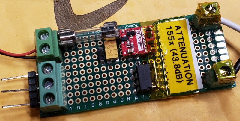
With the right equipment and training, it’s possible to safely work on energized power lines in the 500 kV range with bare hands. Most of us, though, don’t have the right equipment or training, and should take great care when working with any appreciable amount of voltage. If you want to safely measure even the voltages of the wiring in your house there’s still substantial danger, and you’ll want to take some precautions like using isolated amplifiers.
While there are other safe methods for measuring line voltage or protecting your oscilloscope, [Jason]’s isolated amplifier method uses high voltage capacitors to achieve isolation. The input is then digitized, sent across the capacitors, and then converted back to an analog signal on the other side. This project makes use of a chip from TI to provide the isolation, and [Jason] was able to build it on a perfboard while making many design considerations to ensure it’s as safe as possible, like encasing high voltage sections in epoxy and properly fusing the circuit.
[Jason] also discusses the limitations of this method of isolation on his site, and goes into a lot of technical details about the circuit as well. It probably wouldn’t get a UL certification, but the circuit performs well and even caught a local voltage sag while he was measuring the local power grid. If this method doesn’t meet all of your isolation needs, though, there are a lot of other ways to go about solving the problem.


My biggest concern would be the use of perfboard with it’s limited spacing between copper pads. Probably not an issue at 120 – 240 volts, but I would still be concerned about it. Removing the unused pads in, on, and around the HV section might be a good idea.
Quote from the linked blogpost:
“The perfboard layout is also sub-optimal for the sake of isolation. Despite drilling out a row of holes to increase the creepage and clearance distances, it isn’t quite enough to meet regulations, as the clearance is only 3 mm and the the creepage isn’t much better, around 4 mm. This is still more than enough to withstand normal AC line voltages, but there is always a chance that higher-voltage transients will make their way onto the line and the isolation barrier needs to take this into account.”
He just need to use the next size drill bit to make a slot in the PCB. The air gap should provide a much better isolation for that kind of tight spacing. I hope he has also drill out the pads between the two inputs which would also have high voltages between them.
Why does everyone speculate, when the author bothered to take reasonably good pictures? https://ripitapart.files.wordpress.com/2018/11/20181113_182025-e1542158988347.jpg
No isolation between HV inputs, and instead some curious arrangement of 0 Ohm links and higher value resistors..
So nowhere near multi-kV capable in this form, but that’s not the original maker’s intent, 120/240 is more sane.
I’m not sure perf board is even rated for 240V. I definitely would not use it for 240V, but it may be OK at 120V
I live in Canada so 120V is the what this was meant to measure. The NXE1 power module’s only rated for reinforced insulation to 150 Vrms, and basic up to 300 anyway.
But what about spikes on the supposedly 120/240 line? It’s not only the nominal voltage you need to plan for.
I’m aware of the possibility of spikes on the line. I could do something like adding a MOV, but currently I do measurements from behind a surge suppressor.