Craig Lindley is a technical author and a prolific maker of things. This simple project was his first attempt to create a laser harp MIDI device. While on vacation, Craig saw a laser harp with only three strings and decided to improve upon it by expanding it to twelve strings. The principle of operation is straightforward: twelve cheap diode laser modules aim a beam towards an LDR, which changes resistance if the light level changes when the beam is interrupted.
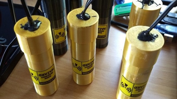
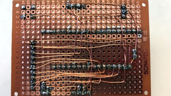
The controller is a simple piece of perf board, with a Wemos D1 mini ESP32 module flanked by some passives, a barrel socket for power, and the usual DIN connector for connecting the MIDI instrument. Using the ESP32 is a smart choice, removing all the need for configuration and user indication from the physical domain and pushing it onto a rarely-needed webpage. After a false start, attempting to use a triangular frame arrangement, [Craig]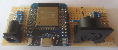 settled upon a simple linear arrangement of beams held within a laser-cut wooden box frame. Since these laser modules are quite small, some aluminium rod was machined to make some simple housings to push them into, making them easier to mount in the frame and keeping them nicely aligned with their corresponding LDR.
Sadly, the magnetic attachment method [Craig] used to keep the LDRs in place and aligned with the laser didn’t work as expected, so it was necessary to reach for the hot glue. We’ve all done that!
An interesting addition was using an M5 stack Unit-Synth module for those times when a proper MIDI synthesiser was unavailable. Making this luggable was smart, as people are always fascinated with laser harps. That simple internal synth makes travelling to shows and events a little easier.
Laser harps are nothing new here; we have covered plenty over the years. Like this nice build, which is more a piece of art than an instrument, one which looks just like a real harp and sounds like one, too, due to the use of the Karplus-Strong algorithm to mimic string vibrations.