[TheSignalPath] wanted to repair a broken Instek PSW80-40.5 because it has a lot of output for a programmable power supply — 1,080 watts, to be exact. This isn’t a cheap supply — it looks like it costs about $2,200 new. The unit wasn’t working and when he took it apart, he found a nasty surprise. There is a base PCB and three identical power supply modules, and virtually no access without disconnecting the boards. He continued the teardown, and you can see the results in the video below.
Each of the power supply modules are two separate PCBs and the design has to account for the high currents required. The power supply is a switching design with some filtering on the motherboard. One of the boards of the power supply module rectifies the incoming line voltage to a high DC voltage (about 400 volts). The second board then does DC to DC conversion to the desired output.
Although it was hard to get to the boards in operation, the theory was that since the three modules were the same, it should be easy to figure out which module was bad, and even which of the two boards in the module. The modules are more or less self-sufficient although there is a controller that requires the center module to provide voltage.
First, he verified the voltages on the motherboard while using an isolation transformer to provide a much lower input voltage. He then tested each module individually using one slot of the motherboard.
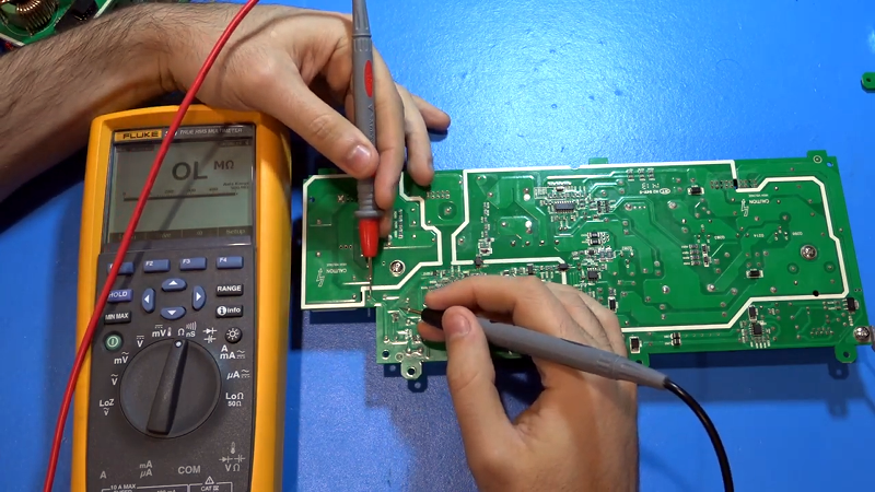
The power supply module that had been in the middle would not start. There wasn’t anything obviously wrong with it. A bit of probing and comparison to one of the good modules, however, finally revealed a failed resistor in the soft start circuit.
He temporarily shunted the open resistor with a similar unit and that made the module start working. That wasn’t the end, though. One of the other modules had some burn marks on it. The area was near some very low-value resistors near a MOSFET. The circuit had a fuse that wasn’t bad, but it looks as though the resistors may have fused before the fuse when the FET shorted out.
We were glad to see someone else stacking SMD resistors to parallel them. We don’t feel quite as embarrassed now about doing that. We also enjoyed all the ad hoc circuit analysis, since there was no schematic available.
While the inside of the supply was compact, it didn’t have that certain glow we enjoy. It did look like better construction than the cheap power supply we tore down that was killing modules when it turned off.


Definitely a current and powerful article.
Ahaaaaa
Yeah, I could not resist reading until the end.
Oh, the video shows the passing of a mammal ESD generator :-D
Am I missing something here? A 1000W PC or mining power supply is something around $75 to $120 USD retail. For this to be $2,200 USD brand new, what does it have that other supplies do not? Presumably variable current and voltage outputs but is that worth $2,100 USD? Is it not a switch mode power supply? Lower noise? The functional differences seem to be fairly minor but the price difference does not!
I’ll try and summarize what you’re missing.
1kW pc psu / mining psu has a main 12V smps circuit in it, and a few dc-dc circuits for powering 5v/3.3v/etc lines. They have no current control besides current monitoring and over-current protection. Computer psus generally are not designed to operate in parallel or series with other psus, unlike this one (3 in parallel, 2 in series by design). Even if you modded a computer psu to give you the ability to adjust voltage, it will not be stable over the whole range of voltages it would support (main factor for upper limit being main output capacitor max voltages).
ATX spec for computer power supplies allows up to 0.6V of tolerance for the 12V rail, while this thing has a 0.09V tolerance max.
The functional differences are far from minor.
3 identical power supplies you say?
I give you this:
https://youtu.be/FcN_ZcztjXo