We know that by this point in the development of CNC technology, nothing should amaze us. We’ve seen CNC machines perform feats of precision that shouldn’t be possible, whether it be milling a complex jet engine turbine blade or just squirting out hot plastic. But you’ve just got to watch this PCB milling CNC machine go through its paces!
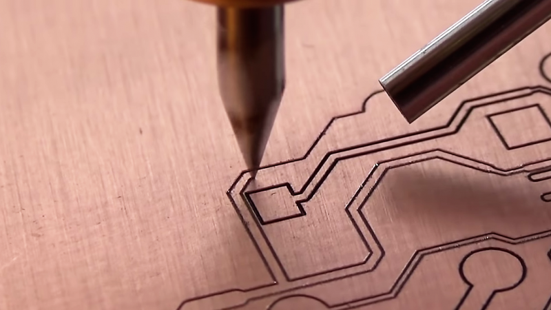
The machine is from an outfit called WEGSTR, based in the Czech Republic. While it appears to be optimized for PCB milling and drilling, the company also shows it milling metals, wood, plastic, and even glass. The first video below shows the machine milling 0.1 mm traces in FR4; the scale of the operation only becomes apparent when a gigantic toothbrush enters the frame to clear away a little swarf. As if that weren’t enough, the machine then cuts traces on the other side of the board; vias created by filling drilled holes with copper rivets and peening them over with a mandrel and a few light hammer taps connect the two sides.
Prefer your boards with solder resist and silkscreening? Not a problem, at least judging by the second video, which shows a finished board getting coated with UV-cure resist and then having the machine mill away just the resist on the solder pads. We’re not sure how they deal with variations in board thickness or warping, but they sure have it dialed in. Regardless of how they optimized the process, it’s a pleasure to watch.
At about $2,600, these are not cheap machines, but they may make sense for someone needing high-quality boards with rapid turnaround. And who’s to say a DIY machine couldn’t do as good a job? We’ve seen plenty of them before, and covered the pros and cons of etching versus milling too.
Thanks for the tip, [rolmie].


looks good
Looks VERY good.
Do you have the wegstr machine? Could you tell me your experiencia with it?
impressive.
I started out by milling PCBs, but ended up moving to presensitized UV boards because it worked so much better – especially if you’re intending to add a soldermask. The soldermask needs UV curing anyway and the more contoured surface of the milled board meant application was uneven. Having said that, this is as good a result as I’ve ever seen from a milled board.
pcb2gcode includes a z-probing g-code option that allows very smooth cuts on a PCB.
However,we had to roll back to version 1.3.2 (sourceforge has a stable version) to get it to work on our local Taig machine.
Nice setup, but people can cut steel stencils now too. ;-)
I use pcb2gcode, but ended up doing the z-probing adjustment in the bCNC host controller software. IT’s very effective and I get very consistent cut depths. I’ve even gone to the point of purposely stressing the board in the hold-downs so that there is a slight 0.5mm curve in it – it makes the board stiffer and better able to resist the vertical forces as the v-bit makes it’s initial plunge cut.
Nice tip, as we usually use 2-sided tape on surfaced MDF with various results.
we include bCNC on the clubs cnc distro for fast GRBL based UV laser photo-plotters (OS rc1 is set for release on Dec 28). However, I haven’t tried using bCNC for kicad 5 PCBs given we run linuxcnc g-code on our mills. =)
If you are open to sharing your experiences, I’d like to post a url or video of your methods in our projects public documentation area. We are trying to document several verified process-pipelines in detail to help people save time perusing manuals, and get their machines dialed-in quicker. We are in the username link as the HaD comment body flags our url as spam for some reason.
Cheers,
J
WOW!
2000€ !
I can see this being used in a R&D office for quick prototyping (would love to have that at work) but it’s way too pricey for a hobbyist.
I tough having one at home but the price made me sad. They should have a cheaper for hobbyists around the globe.
lol there are cheaper ones, they just aren’t nearly as nice. I’d also like a Ferrari for the price of a bicycle too.
Why would you want that? A Ferrari is a lot harder/expensive to maintain and needs to be refueled often.
B^)
Wonder what the tool life and cost is
IIRC, engraving bits are good for about 10 big PCBs, end mills will last longer than that. It also depends on material, HSS bits will be much less durable than tungsten ones, but these are quite fragile and break easily…
Carbide v-mills are cheap, like under $1 each. I get half a dozen boards out of one before they start making ragged cuts – it’s OK with thicker traces and I save fresh bits for finer detailed boards.
From the videos the spindle does not look like it has a collet. There is a set screw. They also refer to a sping loaded engraving bit. If you look on their webpage they sell springs. I expect that this has something to do with how they get results on uneven surfaces.
The springs (5 Euro) are for the old spindle motor only.
It was 7000 rpm only in 2016.
The price for the spindel was 53.05 Euro in December 2016.
The 11000 rpm spindle was 129 Euro in December 2107
The 11000 rpm spindle is 289 Euro now (December 2018)
The whole cnc machine (with parallel port) was 648,47 Euro December 2016.
Look how they have gone crazy now.
Some pics:
https://i.postimg.cc/x8MRmYWm/Wegstr-CNC-2016.jpg
https://i.postimg.cc/j2gF58Tn/Motor-8.jpg
https://i.postimg.cc/RCDdWJft/3-D-Spindelmount.jpg
Hi. Do you have video from machine in operation or photo of finished board? Something to compare with photo/video from the producer?
I wonder, what is the circuitry under the 2560 outline? Does something get soldered there or is it for capacitive loading or something else?
Sometimes chip design calls for ground planes or VCC planes under specific areas of the IC to help with noise rejection or timing, at least that’s what the motorolla HC11 manual says
At first I thought that’s an option for using another chip, you can see that sometimes on PCB designed to accomodate more different packages. But in this case it doesn’t make sense as most traces lead only to pins of larger chip and nowhere else. Maybe it’s place for some kind of header that can be connected to in prototyping phase.
0.1 mm is ~4mil
I want to love this, but my experience with LPKF pcb milling machines (basically expensive boondoggles) makes me very skeptical…
Are they using Mach 4 software on their mill?
There is zero slop in their mechanical drive system. I wonder if they are using ball screws instead of belts.
Yes they use ball screws with slides on both sides.
Could you give a pointer.
Have watched al accessible files and videos.
No ballscrews, no limit switches, the regular stuff.
Give us a link please.
They are more secretive than Apple.
Ask them, they will you not tell ANYTHING you could not see from their pictures.
No pictures, just the orientation of the motors from their stock photos. Motor is in the center of each axis, slides are on both sides. The screws are covered so I can’t say what the pitch is.
I think the key to their success is the software. It resemble Mach CNC software however since I don’t own that high end product I can’t say with certainty. My guess is that they package a customized version.
Just me guessing.
I actually love this because the solder mask is so smooth and shiny! Usually it’s rolled on at the factory and so actually the surface is quite uneven and lumpy. This mirror finish really looks nice!
The springs (5 Euro) are for the old spindle motor only.
I can tell you FIRST hand, no guesswork rrequired.
It was 7000 rpm only in 2016.
The price for the 7000rpm spindel was 53.05 Euro in December 2016.
The 11000 rpm spindle was 129 Euro in December 2107
The 11000 rpm spindle is 289.2 Euro now (December 2018)
The whole cnc machine (with parallel port) was 648,47 Euro December 2016.
Look how they have gone crazy now.
https://i.postimg.cc/j2gF58Tn/Motor-8.jpg
https://i.postimg.cc/RCDdWJft/3-D-Spindelmount.jpg
https://i.postimg.cc/x8MRmYWm/Wegstr-CNC-2016.jpg
Only 11,000 rpm? was the video sped up? I expected them to be in the 100,000rpm range with the travel speeds I was seeing.
I’m using a PCB mill I built myself from the CyclonePCB Factory project. It works quite well but I think my reliable limit is about 0.5mm features. It’s got standard threaded rod drives which perform suprisingly well, and I upgraded the stepper coupling from 3D printed gears to commercial toothed pulleys. Biggest issue is there was a design choice on the X-axis that makes it inclined to wobble, so I get some strange sawtooth cuts when traversing at angles.
The quality of the cuts on that unit looks great and I’d have to make quite a few upgrades to match it.
The G00 speed is low. There’s probably no tool magazine either. The spindle speed has to be very high, but the feedrate is limited. Good only for prototyping. The tool wear rate would be interesting to know, because I bet there’s a lot of rubbing.
We have been using a Chinese cnc3040 machine nearly for 4 years which we aquired from a well known chinese online site. We have been mostly using it in pcb routing but our mechanical eng. tried wood, abs, hipps, aluminum and even steel one time. Although it required some minor adjustment it works great with the diptrace + flatcam + mach3 combo.
After some hard testing we have changed the aluminum bed with the 10mm steel one 2 years ago, and now the machine is nearly rock solid.
I can route 0.4mm traces with 0.2mm engraving bit in 300mm/min feedrate. It can achieve even smaller traces if i turn down the feedrate.
But the whole pcb routing idea can be effected with quality of the bare pcb, the sharpness and quality of the used bit, feedrate, the setup of your machine (if its bolted down to a solid surface or if it is on a table that can shake a little), etc etc.
Yes, the idea of milling 0.1mm routes can be great but you can achive acceptable results with even cheaper options than the WEGSTR. It only requires some fidlleing as such the people done in the K40.
You did exactly what many poeple did after purchasing crappy machines mad frem mostly standard mechanical elelemnts.
As you said, it required much afterwork to fit your needs.
From my observation the Wegstr cnc is a truely ready to use thing.
It gives straight unpack-> setup-> use it experience.
How did they do the Chinese can not or are not willing to do?
Make a SIMPLE design that has all mechanical dimensions, true angles, perpendicularity inherent.
NO adjustments required, aside from bed levelling after heavy usage.
Everybody can do, make a plan, leave out ALL UNNEEDED parts.
Do not add gears, do no put in something that requires set screws, do not add couplings, ball bearings no bushings where not absolutily needed.
The threaded rods, I assume trapezodial only, are a fixed unit with the rotor of the steppers. Good choice.
The frame made fom HPDE,HPDL,POM ro something alike.
Cut out the two basic structural parts on a big cnc mill in one go.
Allow small tolerances only.
That is the cnc is made. K.I.S.S
The secret they try to hide? THERE IS NO SECRET!
Don ‘t get confused by patent claim. It is obviously not the technical solution but the outer experience, same as patent on the rounded edges on dumb iPhone.
It covers the artistic impression only.
BTW. They have refused to tell the patent number. No entries could be found on publicly accessible patent registers.
They id not even tell the mechanical dimension s of the spindle or the mounting holes size and distances.
Open up the machine. You will not find any fancy high tech mechanics or electronics.
No, nada , nothing, niente Nix da.
I have not seen reports about longevity, duarabilty, lifecycle of parts wearing out, etc..
Sure the setprize point is crazy high.
They have hiked the prize over the time finding out how much the customers are willing to pay.
But the targeted customers processing diamonds, brass, gold,and some technical inclined users
are capable enough to pay even more and make even more money using the cnc then.
@Hackaday: I would not put this machine into a hacker related website.
There is nothing to hack.
Nice picture of the spindle.
Do you have a picture of the internals of the spindle motor?
I am very curious.
It looks like a stepper motor frame. But a stepper doesnt do 11000 rpm.
I have seen a video on youtube of a guy who converts an older parallel version to usb.
The parallel version runs on a simple avr (i gues arduino) with 3 simple stepper drivers (polulu)..
So they get very accurate results whith a very simple machine.
The frame seems to be build out of plywood of some sort.
Hi,
put in the link pleas.
No, no.
The structrual parts are definitely not made from wood.
Read my explanation trough.
See the pictures, their advertising videoas.
They have mentioned the used materials somewhere.
From my recherche the guy leading the company has absolut no background related with developing electronics or mechanics.
Search for his postings on several “social” crapp nets.
He responded very bad when i asked him about his qualification, developing this cnc.
From y assumption:
He managed to find the money (bankers, share holders, donators) to make the invention of probably a single talented man a commercial success.
Sometimes the Internet Wayback Archive helps you out finding old website content, the operaters do not want to be visible any longer.
Does someone knows how the small rods that connect the two layers are called ?
I believe what your referring to are called rivets.
Give me the money to buy a second one, I could chop it in two halfs then ;-)
So, external pictures from the view only.
But some knowledge of stepper motors internal give the missing information.
Just do the combination of available informations, put them in a pot, stear it and voila, You get the idea.
This is how reverse enginering works.
Please look at the pictures and the drawing I have made from the measurements.
The spindlemotor has the same faceplate size as a 17NEMA stepper motor.
The long shaft portion of the case has the front bushings , I assume two in a row.
If had done very carefull the two bearing are of different types.
The foremost a preloaded diagonal ball bearing then, the second has a regular radial ball bearing.
Both combined are guiding the front end of the rotor and reduce the axial play.
This is problem on the shafts of cheap Chinese made air or watercooled cnc spindles.
All the same crap on 200Wa up to 3kW spindles, can be seen many times, many play weak runout.
The room inside the spindlemotor is not big enough to hold a dual bearing at the back end of the drive shaft.
So there will be a single ball bearing only.
Very sad, they had glued in the BEC in the factory.
This (now internal) electronics makes the brushless motor easily usable by feeding 26volts DC in only.
https://abload.de/img/1swf0j.jpg
https://abload.de/img/2f5fmv.jpg
https://abload.de/img/3z4iu7.jpg
https://abload.de/img/489el3.jpg
https://abload.de/img/5nwfo8.jpg
https://abload.de/img/6jzim9.jpg
https://abload.de/img/7rfi96.jpg
https://abload.de/img/8opc51.jpg
https://abload.de/img/985iwq.jpg
https://abload.de/img/13d5fmh.jpg
https://abload.de/img/3dmodelsizey7er3.jpg
https://abload.de/img/motoranschluss49cgo.jpg
https://abload.de/img/smallnema17steppermotl0d9d.jpg
https://abload.de/img/0j2292.1200x1ei1.jpg
Youtube video on converting Wegstr CNC for use with Mac & Windooze
Maker MarkusFuller
https://www.youtube.com/watch?v=D3O2jpXJVDU
Picture taken from Markfullers converdion video.
I have cleaned up to make it better viewing.
Inside overall viw from top.
Initially when I had seen the machine first time it looked like a HP Desket 500.
Is this the design they have copied without permission.
IS THIS THE SECRET?
Hu?
https://abload.de/browseGallery.php?gal=iZdBkVur&img=wegstrcnc2016insidelpa4f6q.png
Please excuse me for the quick to much reply.
After having seen the conversion video it is plain to see, at least the shown machine was made from pixelboard.
Glued masking tabe around the edges.
Plus, the ugly faulty electronics pcb. Many hacker do much better at home.
This is something companies put in 5 Dollar kitchen timers since ages.
And for sure this i nothing they want the customers to know, at least not before purchasing a machine.
Germans have a saying: Assen hui, innen pfui.
.
There has existed an earlier version having a 4000 rpm spindle only.
See the pic.
https://abload.de/img/wegstcnc4000rpmspindl74coz.jpg
Außen hui, innen Pfui :)
Hello. So what do we have on the spindle? I have only one idea, there is an overlay on top to hide the upper bearing and prevent the lubricant from spreading. Bottom is also a pad with a seat for 1-2 bearings to reduce runout. The most important thing that inhibits my ideas is that this is most likely a stepper motor. And one of the two or there is not the number of turns that is written or it is not a stepping motor. Who has any opinions on this?
i thought it was a rewired stepper. (change it to 3 phase and run with an esc) but a nema 17 has only 8 terminals(stators) inside instead of 9. so i think that isnt it.
perhaps the internals are removed and changed by a brushless motor?.
i have seen nema stepper motors on the net capable of 4000 rpm but these have rather bulky drivers.
maybe it is an rewired stepper with new metal sheets to create 9 stators (explanes the high price for the spare spindle motor).
and since it is a rather small motor the esc wil fit on top.
a nema 17 is out of the box a good solid motor with preloaded bearings, so they added extra bearings at the bottom to compensate for the extra forces the milling ads.
can someone tell me linear motion mechanism (linear bearing type) used in wegstr and where to buy it?
X and Y axis are just solid square Aluminimum extrusions, and the Z-axis is Aluminimum U-profile. Bearings are just sliding plastic blocks. There are a few reviews on Youtube in which this can be seen.
This Wegstr thing may have been a reasonable tool if it was sold for less then EUR500. It definitely is not worth what they are asking for it. You can easily build something better from MGN12 rails and some pieces of sheet material. Painted MDF or plywood may work. (Painted to seal moisture content and therefore lower deformation over time.)
Do you know if the top bed plate is held down in place by something more than the X axis lead screw/lead screw nut?
My spindle motor become faulty there are some replacement parts that not require to expend like 400EUR? many thanks