We’ve got two hands, so it’s natural to want to use both of them while diagnosing a circuit with an oscilloscope. Trouble is, keeping both hands on the probes makes it a touch difficult to manipulate the scope. If only there were some way to put your idle lower appendages to work.
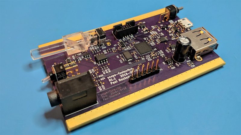
This multipurpose oscilloscope footswitch interface makes so much sense that we wonder why such a thing isn’t standard equipment on more scopes. [Paul Roukema]’s interface relies on the USB Test and Measurement Class (USBTMC) protocol that allows most modern scopes to be remotely controlled, somewhat like the General Purpose Interface Bus (GPIB) protocol of old. [Paul]’s interface uses an STM32 microcontroller to talk USBTMC to either Keysight’s Infinium scopes or the Tektronix DPO line, since those were what he had to test against. Tapping the footswitch cycles the acquisition mode on and off or triggers a single acquisition. He’s thoughtfully included the USBTMC specs in his GitHub project, so adapting it to other scopes should be straightforward. We’d even wager that older scopes with GPIB could enjoy the same handsfree control.
Have a down-market scope but still want to go handsfree? [Jenny List]’s primer on running a Rigol with Python might offer some hints on where to start.


Neat! I took on a similar project at work and went with SCPI over TCP or UDP. It requiring a network with DHCP makes it a lot more infrastructure-reliant unfortunately. This is so much cooler ????
Scopes don’t take voice commands yet? How … 20th century.
Keysight Infiniivision 6000 series has voice control built-in.
I was looking for something a bit less than $14,800. RPi & Alexa is more like it.
See https://hackaday.com/2016/03/29/you-speak-your-scope-obeys/ ;)
I worked on a project for Ben Heck that hooked up Alexa to a scope using a Pi and ethernet port. Not super fast since it has to go up to the cloud and back down again, but it worked. https://youtu.be/fN5wYORbWQM?t=736
A 2018 ‘scope should misinterpret your voice commands, ignore you when you have a cold, and spy on your sexual habits in order to serve you advertisements. How quaint!
“makes so much sense that we wonder why such a thing isn’t standard equipment on more scopes. ”
Because most people don’t try to hold 2 probes with two hands. There are many other ways to connect a probe to a signal path than to “hold it”
Exactly, the clips on most probes are there for a reason…
That’s like thrice the time, half the limb efficiency and one full headache when unclippable smd contacts are involved :D
Clips are fine … at low frequencies.
High speed probes tend to be much harder to hold. It doesn’t help that a lot of high speed signals are differential (meaning the differential probe had to be held at exactly the right angle otherwise it won’t contact both sides at the same time). This gets much worse if you need to look at two differential signals at the same time.
For a subset of my designs, I need to use a microscope to position the probes.
I use very low tech voice commands – I ask the engineer at the next desk to come over and press the RUN/STOP button (or whatever) when I want to save a trace.
Exactly: active probes, plain PCB test points (no pins), and bugging the engineer the next desk over has been the order of the day. The last part starts getting old for everyone pretty quick, and what if you are working late?
Good points. That sort of stuff is out of my league, so not something I thought about.
In my experience, when you have a limited amount of hands, the clips will fail their grip as soon as you try to do a measurement. I would not be surprised if foot switches will become part of the standard lab equipment in the future.
Not surprisingly at the first Hack A Day NYC event I did see a Rigol scope controlled over USB via an appropriate platform. I was impressed. But the hosts (You know who you are!) were surprised by my gadget.
Most scopes fancy enough to speak USBTMC also have active probe interfaces, that row of extra contacts around each channel’s BNC connector. Some of the official probes have a squeeze-button on the side, that can be mapped to functions like this. I don’t know if anyone’s got the pinouts for how they do that, but I’ve used some of those fancy probes and I can attest to how useful this feature is!
As to the instant project: Could this be instantiated as a software module that would just run on a $5 RasPi and hook the footswitch to some GPIO? As much as I love seeing what looks like a eurocard-footprint PCB that’s gonna slide into a really fancypants Hammond box with end plates and everything, I feel like this could be more accessible if it was purely off-the-shelf hardware, yeah?
Even your basic Rigol speak (broken) USBTMC these days, so it’s fairly universal. Just have to actually get one to test with.
It could definitely be done on an RPi with some code using python-usbtmc, and it would be a lot cheaper that way. A lot less custom code too, But I don’t get to do too much PCB design or embedded firmware for my day job (FPGA Design), so things like this are my way of staying current. It does indeed fit in a Hammond 1455C801 case too, although I’ve actually found an option on AliExpress that is both cheaper and better made. I say this with great sadness since Hammond manufactures right in my neighborhood.
I loved the early HP format probes that came with the multimeter version of the HP1742A which was my main instrument since it was first announced bought it within a month. Those probes offered a plastic shroud DIL test adaptor so you could firmly place the thin sharp pin active line onto an IC pin without it sliding off causing a possible short, a fine thin yet strong gabber which went around the pin with enough clearance so it wouldn’t touch the pins either side and had excellent holding force, a two prong spring loaded type where the ground ref at convenient distance for PCB’s with DIL chips and of course a shrouded clipon ground lead.
These days I would expect all of these probe types and augmented variations would be available in many different types of kits and at least for BNC and SMA connectors from the largest 3D printer in the world though only for about another year which includes subsidised international postage…