Many a budding electronics maker got their start not with a soldering iron, but with the humble breadboard. With its push connections, the breadboard enables electronics experimentation without requiring the specialised skill of soldering or any dangerous hot tools. What it lacks is a certain robustness that can make all but the simplest projects rather difficult to execute. [Runtime Micro] have shared a few tips on making things just a little more robust, however.
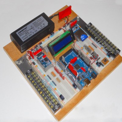
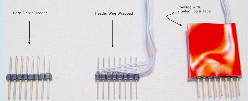
The fundamental principle behind this process is replacing point-to-point jumper wires with custom cables, made using 0.1″ pitch headers and wire-wrapping techniques. Other techniques include pinning down components with Blu-tack, and selecting components with the appropriate wire diameter to avoid them falling out of the breadboard’s spring clip contacts. There are also useful tips on using foam tape for appropriate strain relief.
While breadboards aren’t really suitable for projects dealing with high frequencies and can rapidly become unmanageable, these basic techniques should improve a project’s chance of success. These simple ways of improving connection quality and reducing the likelihood of things falling apart are likely to reduce frustration immensely.
However, once a maker has a taste for corralling electrons to do their bidding, soldering should be the first lesson on the agenda.
[Thanks to stockvu for the tip!]


Wirewrapping is a sturdy reliable construction. Shame to build it on top of breadboard. Think of castles built on sand.
One of my mottos is that solderless breadboards are the work of the devil. I refuse to try to help anybody that has built a circuit using them, since you spend more time debugging the breadboard than you do debugging the circuit.
Much better to do as the masters do, and use soldered manhattan and rat’s nest techniques.
I’ve seen true “masters” use breadboards in flawlessly working factory floor equipment, I’ve also seen hacks use breadboards with power parts and create melted modern art. Ive also seen hacks solder a crimp, because they don’t know how, or have the tools, to crimp properly. Knowing when and how to use various tools/techniques is part skill, knowledge, experience, and craftsmanship. Neatness counts and does make breadboards a very handy tool. When asked to help and I see a scruffy breadboard, we have “neatness” leaning moment before proceeding. ;)
Umm…learning, not leaning.
There are breadboards and breadboards.
As usual, the old ones and the modern (chinese) ones are not the same.
The old ones with beryllium copper contact-springs and good plastic are super-reliable.
Even if , and that’s a big if, the contacts are have a repeatable resistance, that’sa small part of the problems with solderless breadboards.
Lack of skills/experience/knowledge of proper parts/termination goes hand in hand with being a newbie.
There’s also a big difference from a $2 “breadboard” and a proper breadboard.
masters dont use manhattan ..old fools who think rf design is just a craft project use manhattan .
Ok then… what do “masters” use?
Manhattan is pretty good for one-off sub-GHz RF projects – easy to do, make measurements, rework or modify, yet also solid enough to go into service. Of course, as interest in radio, and in working with discrete components, wanes, there’s going to be less and less use of Manhattan.
“masters” uses the best technique for a given project.
That is probably breadboard for simple / low frequency projects, test circuit board for more demanding ones, Manhattan when applicable and custom PCB when needed (and yes this list should include every technique, even this old and obscure one only three people in the world mastered back in the 60’s, but you got the idea).
A “master” can do anything with his golden hammer. But he / she knows that if it was possible, he / she should have used the best method, and not the one he / she masters the most.
And this ladies and gentleman is what we call a troll. Well played sir, I see you even got a couple of people to feed you.
The display panel of every F-16 and EF-111 had wire-wrapped display panels, and it is also used in the C3 systems. Worked on these in the late 70s/early 80s. Wirewrapping, when done right, will outlast the thing it goes into.
Tape is fine for temporary connectors, when I need them for a longer time I put on hot glue.
Even just some tiny slices of heat shrink can be easier to apply and easier to remove than tape.
Large diameter heat shrinks are available and they can be used to protect modules or in this case the “plug”. Tape are not for anything long term as they can degrade.
Might also want to look into IDC (Insulation Displacement Connector). e.g. DIP plugs, dual row connectors
They can be used to make connection to dual row headers. e.g. RPi
https://hw-by-design.blogspot.com/2018/08/smt-header-ic-socket-header-plug-for.html
Also look into SIP/DIP resistor array, BAR graph LED etc. They can make breadboarding a lot easier.
thanks for that link! (DIP socket + SMD header)
I’ll be adding that to my bag of tricks :)
gottalove resistor network SIPs paired with LED bargraph if tidy is the goal. nice suggestions !
Re: SIP/DIP resistor arrays. They come in bussed version as well as independent ones. The bussed ones are great for pull-ups/down or for bargraph LED current limiting. One side of each resistors is connected together for you saving the mess of extra 8-15 wires.
Also the trick of labeling your breakouts:
– print a few lines signal names in 6 point fonts
– roll them around your wires
– put transparent heat shrink on them
https://2.bp.blogspot.com/-6QfOr-wcKpE/W66fZ63r43I/AAAAAAAAC4w/j2Vzy8aRKUAOT4X2nGq4VmJjq3502oiDQCLcBGAs/s640/IMG_2424.JPG
The wires in those “Dupont” cables aren’t that great, but you can make your own from the housing and crimp pins (which is what I did.) You can also buy “Connector 2.54mm Pitch” similar to those single row PC fan power connector. They come in 2-11 pins. They are available as kits too.
Nice.
In my opinion dupont connectors are utter garbage. If the connector get twisted on a pin the internals of the connector itself become all mangled. I much prefer the “dupont style” jumpers with the rounded pins instead.
Huh?
Why not just use ribbon cables with IDC connectors, which come in various widths from 2 pins to 40+, and then use headers to connect them to the breadboard.
Exactly. I have seen so much whining about dual row headers. I guess they don’t know about IDC DIP plugs.
Yup. I use a salvaged DIL floppy-disk ribbon as a breakout cable for Raspberry Pi.
On the main topic, I bought an old 300-in-1 experimenter kit – which contains a central breadboard in a custom plastic console with various buit-in components, then mounted a proper multi-volt power supply, some more LEDs, a 20×2 LCD display, etc. Not as cool as the OP, but it has been useful.
My goal was to make it faster and more convenient to try ideas; I’ve never considered breadboards as more than a sketchpad for trying things.
You probably mean IDE ribbon cable. The floppy ones do not have enough pins for the PI
Way back machine not working? Snicker. 26pin on old PI-1 A and B-1 . Pooched it myself below. Meant to say 50 wrote 40 thinking 34 but should be 26 but now 40. Figure that.
Is proto space. Clear boxing/packing tape. Extremely sticky and somewhat grimy proof. Also good for labeling leads. Printout on paper. Slap packing tape cheap laminate on paper label and cut. Leave one side bare paper and can white glue around wire or tape again. Keeps labels clean and can make them larger. I prefer parallel to wire. Foamy tape works but need 3M or better or just dont stick long. Hot glue is useful but so many .1 connectors being tossed from old hardware like floppy, serial, parallel ports, usb headers, and IDE/PATA as has been said. Again a halfway decent crimping tool or at least a bench press helpful but channel lock pliers will work. With that the headers can also be used as tiny breadboards themselves. Proper wire size between header punctures and flow some solder. Another use is to crimp onto a piece of soda bottle plastic for attaching to whatever and becomes convenient spot to put leads temporary not on main board space. Of course most are dual inline and female. Male pin rows are cheap or can salvage from old hardware too. Recycle them old boards.
Elenco still making those X-in1 kits but dont say Radio Shack on ’em anymore and prices gotten stupid. Use the 40pin on PI-2 B . Heat shrink off the remaining sockets and makes a partially keyed attachment. I say partially due to some ass try to force in no matter what is done to prevent.
I think all the one-upmanship, “I do it this way..” and “here is some obscure technique” comments on this and many a similar post is really trying to say:
“Hey community and HAD writers, make a series on all the various prototyping methods for beginners to intermediate, with pros and cons of each style”.
This guy has some pretty cool ideas for breadboard prototyping. It reminds me of one of my favorite Instructables (https://www.instructables.com/id/My-Top-Ten-Most-Useful-Breadboard-Tips-and-Tricks/.) Combining these (plus the comments here and in the ‘Ible) and you have some really powerful prototyping tools.
I videoed a technique I haven’t seen anywhere:
https://youtu.be/DM5jIb9fmwA
Wow, very cool idea. It looks like this could be used to “encapsulate” other things also.