Vectron Adds Basic And Christmas Tree Control

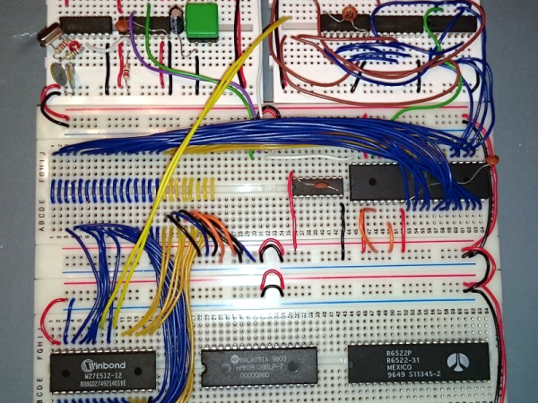
Not content to leave things alone, [Nick Bild] has updated his nearly practical breadboard 6502 Vectron project once again by adding Tiny Basic and home tree automation. Instead of using an LCD module like last time, or his custom-built VGA output using 7400-series logic, [Nick] chose to go modern this time and implemented a VGA output using a TinyFPGA BX.

Tiny Basic was one of the first versions of Basic released after Bill Gates famous open letter to hobbyists in 1976. While Altair Basic was selling for $150, Tom Pittman wrote Tiny Basic for the 6800 and sold it for only $5 (don’t worry, Tom has since made it free to use). We got a kick out of browsing the Tiny Basic manual and learning that our serial number can be found on the paper tape leader, and that a Teletype will generally receive one more character, at least, after getting the X-OFF control signal.

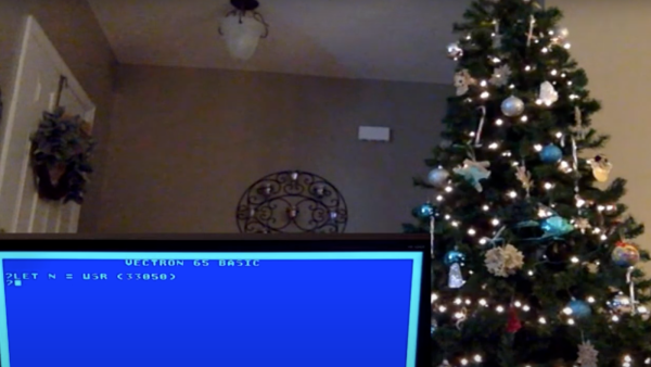
In the video, you can see [Nick] running a short Basic program and operating his Christmas tree lights from the Vectron, although it’s only on-off control. He suggests that a PCB version is in the works, but he’s having trouble deciding when to quit adding features.  That’s a conundrum we know all too well.

Continue reading “Vectron Adds Basic And Christmas Tree Control”

Fail Of The Week: Z-Tape Is No Substitute For Solder

Here at Hackaday, we see all kinds of mechanical construction methods. Some are impressively solid and permanent, while others are obviously temporary in nature. The latter group is dominated by adhesives – sticky stuff like cyanoacrylate glue, Kapton tape, and the ever-popular hot glue. They’ve all got their uses in assembling enclosures or fixing components together mechanically, but surely they have no place in making solid electrical connections, right?

Maybe, maybe not. As [Tom Verbeure] relates, so-called Z-tape just might be an adhesive that can stand in for solder under certain circumstances. Trouble is, he couldn’t find the right conditions to make the tape work. Z-tape, more properly called “Electrically Conductive Adhesive Transfer Tape 9703”,  derives its nickname from the fact that it’s electrically conductive, but only in the Z-axis. [Tom] learned about Z-tape in [Joe FitzPatrick]’s malicious hardware prototyping workshop at the 2019 Hackaday Superconference, and decided to put it to the test.

A card from a Cisco router served as a testbed thanks to an unpopulated chip footprint. The 0.5-mm pin spacing on the TSOP-48 chip was within spec for the Z-tape, but the area of each pin was 30 times smaller than the recommended minimum bonding area. While the chip was held down mechanically by the Z-tape, only five of the 48 pins were electrically connected to the pads. Emboldened by the partial success, [Tom] tried a 28-pin SOIC chip next. The larger pins and pads were still six times smaller than the minimum, and while more of the pins ended up connected by the tape, he was unable to make all 28 connections.

Reading the datasheet for the adhesive revealed that constant pressure from a clamp or clip might be necessary for reliable connections, which suggests that gluing down SMD chips is probably not the best application for the stuff. Still, we appreciate the effort, and the fine photomicrographs [Tom] made showing the particles within the Z-tape that make it work – at least in some applications.

Making Your Breadboard Projects A Little More Permanent

Many a budding electronics maker got their start not with a soldering iron, but with the humble breadboard. With its push connections, the breadboard enables electronics experimentation without requiring the specialised skill of soldering or any dangerous hot tools. What it lacks is a certain robustness that can make all but the simplest projects rather difficult to execute. [Runtime Micro] have shared a few tips on making things just a little more robust, however.

Applied correctly, these techniques have the added bonus of making a project neat, tidy, and easy to troubleshoot.

The fundamental principle behind this process is replacing point-to-point jumper wires with custom cables, made using 0.1″ pitch headers and wire-wrapping techniques. Other techniques include pinning down components with Blu-tack, and selecting components with the appropriate wire diameter to avoid them falling out of the breadboard’s spring clip contacts. There are also useful tips on using foam tape for appropriate strain relief.

While breadboards aren’t really suitable for projects dealing with high frequencies and can rapidly become unmanageable, these basic techniques should improve a project’s chance of success. These simple ways of improving connection quality and reducing the likelihood of things falling apart are likely to reduce frustration immensely.

However, once a maker has a taste for corralling electrons to do their bidding, soldering should be the first lesson on the agenda.

[Thanks to stockvu for the tip!]

A 6502 With A Custom Language

The 6502 has a long history with hackers. The Apple computer (the one with no keyboard or even case) had a 6502. So did the Kim-1. [Dolo’s] version is a bit more refined, though. He started it a few years ago in response to one of our contests, but he’s been making improvements to it ever since. In particular, the custom programming language, Dflat, has many improvements lately, including true functions and high-resolution drawing.

The hardware has a CPU running at over 2.5 MHz, 44K of RAM, 16K of PROM, and 16K of video RAM. There’s plenty of I/O, including a keyboard, sound, and joysticks. An SD card provides mass storage and it all goes in a hacked BBC Micro case. You can see an overview video, below.

Continue reading “A 6502 With A Custom Language”

Electronic Prototyping With A 3D Printer

It would be nice if your 3D printer could spit out PC boards. There’s been lots of work done to make that happen, mostly centered on depositing conductive material, although we’ve been surprised no one has worked out how to just 3D print a plastic resist mask.

We recently found a GitHub group for [PCBPrints] which has small modules that would be useful in prototyping and breadboarding. They are really just carriers that create plug in modules for switches, LEDs, and the like. It looks like this is a aggregated list of other GitHub projects that realize these designs. The group is in Spanish, but Google Translate is your friend, as usual. You can see a video of one of the button modules in action, below.

Continue reading “Electronic Prototyping With A 3D Printer”

Chaos Theory In Practice: Chua’s Circuit

Chua’s circuit is the simplest electronic circuit that produces chaos—the output of this circuit never repeats the same sequence, and is a truly random signal. If you need a good source of randomness, Chua’s circuit is easy to make and is built around standard components that you might have lying around. [Valentine] wrote a comprehensive guide which walks you through the process of building your own source of chaos.

The chaos of Chua’s circuit is derived from several elements, most importantly a nonlinear negative resistor. Unfortunately for us, this type of resistor doesn’t exist in a discrete form, so we have to model it with several other components. This resistor, also known as Chua’s diode, can be created with an op-amp configured as a negative impedance converter and a couple pairs of diodes and resistors. Other variations such, as the schematic above,22`01 model Chua’s diode using only op-amps and resistors.

The rest of the circuit is quite simple: only two capacitors, an inductor, and a resistor are needed. [Valentine] does note that the circuit is quite sensitive, so you might encounter issues when building it on a breadboard. The circuit is very sensitive to vibration (especially on a breadboard), and good solder connections are essential to a reliable circuit. Be sure to check out the Wikipedia article on Chua’s circuit for a brief overview of the circuit’s functionality and a rabbit trail of information on chaos theory.

Hackaday Links: January 5, 2014

hackaday-links-chain

While we can’t condone the actual use of this device, [Husam]’s portable WiFi jammer is actually pretty cool. It uses a Raspberry Pi and an Aircrack-ng compatible dongle to spam the airwaves with deauth packets. The entire device is packaged in a neat box with an Arduino-controlled LCD and RGB LEDs. Check out an imgur gallery here.

You can pick up a wireless phone charger real cheap from any of the usual internet outlets, but try finding one that’s also a phone stand. [Malcolm] created his own. He used a Qi charger from DealExtreme and attached it to a 3D printed phone stand.

A while back, [John] noticed an old tube radio in an antique store. No, he didn’t replace the guts with a Raspberry Pi and an SD card full of MP3s. He just brought it back to working condition. After fixing the wiring (no ground cord on these old things), repairing the speaker cone, putting some new twine on the tuner and replacing the caps, [John] has himself a new old radio. Here’s a video of the complete refurbishment.

Here’s a Sega Master System (pretty much a Game Gear) running on an STM32 dev board. Also included are some ROMs for some classic games – Sonic the Hedgehog, Castle of Illusion, and The Lion King. If you have this STM Discovery board you can grab the emulator right here.

[Spencer] wanted a longer battery life in his iPhone, so he did what any engineering student would do: he put another battery in parallel.

Breadboarding something with an AVR or MAX232? Print out some of these stickers and make sure you get the pinouts right. Thanks, [Marius].