 The year is 1894. You are designing a train system for a large city. Your boss informs you that the mayor’s office wants assurances that trains can’t have wrecks. The system will start small, but it is going to get big and complex over time with tracks crossing and switching. Remember, it is 1894, so computing and wireless tech are barely science fiction at this point. The answer — at least for the New York City subway system — is a clever system of signals and interlocks that make great use of the technology of the day. Bernard S. Greenberg does a great job of describing the system in great detail.
The subway began operation in 1904, well over 30 years since the above-ground trains began running. A clever system of signals and the tracks themselves worked together with some mechanical devices to make the subway very safe. Even if you tried to run two trains together, the safety systems would prevent it.
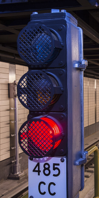
On the face of it, the system is very simple. There are lights that show red, yellow, and green. If you drive, you know what these mean. But what’s really interesting is the scheme used at the time to make them light.
Smart Rails
These days we make everything “smart.” If it were done today, the tracks would be billed as smart tracks because they can tell if a train is on them. The system was built with 1,000 foot blocks of track that are electrically isolated from each other. The total system in New York has almost 15,000 blocks. If a train has wheels on a block it will short the two rails in that block together. Without the train, the two rails show as an open circuit. So each block (sometimes called a circuit or a section) is basically a switch where the train itself completes the circuit.
On a single piece of track, a particular signal will turn red when a block is occupied. Adjacent blocks may also turn red based on how long it takes to stop a fully-loaded train. For the New York subway, a red light also raises a train stop which is a T-shaped bar that is usually just at track level. When the light is red, the bar will engage a trip cock under each car. The trip cock removes power from the wheels and applies emergency braking. So — barring some sort of mechanical failure — a train trying to pass a red light will stop even if the engineer doesn’t want to stop.
Up until 1970, trains would sometimes override the train stop mechanism. This was made against the rules after — you guessed it — there were several collisions caused by overriding the safety system.
History and Evolution
Once you know where there is a train, you get into the subject of interlocks. The idea is that you shouldn’t be able to operate the tracks in an unsafe manner. So if you light a signal green for a piece of track that crosses another piece of track, the second block must be both empty and red. Enforcing this kind of behavior is the job of interlocking.
Interlocking started in Britain. In June 1856, John Saxby received the first patent for interlocking switches and signals. In 1868, there was a patent for what is known today in North America as “preliminary latch locking”. By 1873, well over 10,000 mechanical locking levers were on the London and North Western Railway.
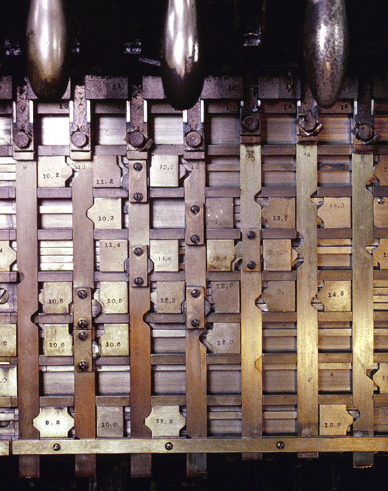
Up until the 1950s interlocking machines used levers like the shown here that locked each other out and, apparently, some of those are still in use, but they now mostly use at least relay logic. All this, of course, is not unique to the New York subway.
Simulation

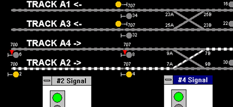
In addition to the fantastic guide linked at the top, Bernard Greenberg also wrote NXSYS which is a faithful simulation of operating the New York City subway system. You can see part of an NXSYS screen here. According to Bernard:
NXSYS can be viewed, utilized, or enjoyed at any of four levels:
- An entertaining rapid-transit video game for those who love the subways and wish to recreate the experience of navigating the tracks, and learn more about the subways and their signals.
- A comprehensive, interactive learning tool for the operation of rapid transit signalling and NX/UR control towers sufficiently detailed and accurate to be of value to those actually responsible for operating such equipment.
- A detailed guide to the sample implementation of such systems in electrical relay logic, observable in action down to the relay level.
- An interactive computer-aided design (CAD) tool for designing and debugging your own interlockings and signal circuitry.
Low High Tech
Pretty impressive. Even more impressive is that this whole thing could be done with levers and relays back in the old days. You can see an interlocking panel in the video below. Of course, the system gets all kinds of upgrades and you can read a lot of detail on all the technology in the subway on Wikipedia.
If you like this topic, you can check out what the British did — after all, it was their idea to start with. We’ve actually talked a little bit about block sensing trains before in a disruptive way.
Photo credits:
- Signal by Metro Transit Authority of the State of New York CC-BY-SA-2.0
- Interlocking levers by [JoeRoma] CC-BY-SA-2.5


Thanks, some of the old timers were great, have ran across this before and always amazed
Just goes to show you, thing could be done before arduino.
Mechanic interlocking is still very much alive, and I used to work on the London underground where it still is. Signal/points lever frames like the picture you have are still used as they are proven tech and it is fail safe. Something that is very hard to prove or assume with electronics and software. Software/electronic based interlocking systems do exist and were trialled in the underground in the 1980s at Neasden depot – a train depot not having passengers can afford an accident, so the theory goes, but don’t tell the drivers – joking aside, depots are low speed and intrinsically safer to use such interlocking. The train stop/cock system is also used on the underground, most likely invented there as we had the first underground ailway in 1863, albeit with steam trains. All signal/points/train stops and track detection relays use a combination of pneumatic, electrical, spring tension and gravity for operating and sensing to ensure all failures cause a safe condition (it will in essence just stop everything or turn it to the ‘danger’ state).
In 1975 in London, Moorgate Terminus, a driver attempted to extend the line by brute force, apparently not slowing down or taking any action to reduce speed before hitting the wall. 43 people died. Lessons learned from that were put in place in Toronto and probably every other similar system using blind, timed trip cocks into subway terminal stations to provide ample opportunity to stop a train. All the terminus crossover signals are timed to the max. A train will approach at controlled speeds.
Video on how legacy block and interlocking subway signals work: https://www.youtube.com/watch?v=i342pCPvSh0
Yep. In London the new system was implemented at all terminal stations and called TETS : Trains Entering Terminal Stations. The train speed was measured by timing the speed at which track occupancy was detected and anything over 8MPH would cause the relecant signalto go red, this tripping the train and stopping it. The driver has no override capability when a train is tripped and it will always apply brakes until at a stop. Railway safety has always been ‘progressive’ : each accident is assessed and new measures out in place to prevent future ones like it. The Moorgate driver acted specifically and it was suicide, whuch is always difficult to prevent when humans deliberately try to kill themselves and others.
A brute force example!
https://fr.wikipedia.org/wiki/Accident_ferroviaire_de_la_gare_Montparnasse#/media/File:Train_wreck_at_Montparnasse_1895.jpg
The physical interlock system is very interesting as it’s a physical implementation of Boolean logic. I do wonder if they are using eletromechanical relays, moved to solid state relays or dumped it and went with straight up NMOS/CMOS chips. Any way it goes, I certainly hope (though suspect) they are checking for component failures and have redundancies in place. CPUs are great but I’m not even sure it’s possible to ensure they will fail entirely before providing the wrong output.
When it really is important for a system not to fail, usual practice is to build 3 implementations with more or less nothing in common other than that it does the same thing, then use majority logic to make sure all 3 agree and flag an error if they don’t.
Some solid state interlocking systems do indeed work that way, as do other safety critical architectures. The alternative is to have 3 identical systems in the voting and majority rules the decision, the idea being that some hardware/sensor fault knocked out one of the identical systems. Boeing use one architecture, Airbus the other. It is a philosophy and you can see the pros and cons of each. If you agree that most errors are at the requirements definition stage then one philosophy is better than the other, however if you believe most errors are in the implementation phase then the other philosophy is better. I say ‘better’ when what I really mean is ‘what some people think’. Certainly something like Ariane 5 would have benefitted from 3 different implementations. And of course, you don’t want the things constantly voting right and wrong either, so getting reliability correct with voting systems can be difficult.
Also, although insulated track sections are still used (with insulators called block joints) they are costly to maintain, and so a block-jointless method started to be used in the late 1980s whereby each track section is a tuned frequency loop to ensure current flows in a ‘virtual loop/circuit’ even though there are no insulators between track sections.
https://www.wikiwand.com/en/Track_circuit
And not a 555 in sight.
So the new meme would be “meh, should have engaged a trip cock”.
This track section signaling scheme is still used in Poland It’s also common in other countries, but in case of Poland it sometimes fails to work properly. For example one time in winter I had to wait four hours for a train because section of track was shorted out at railroad crossing and generated “slow down” signal for all the trains approaching that crossing. How this happened? Simple stupidity actually. In Poland to keep roads safe we use ordinary table salt, as it’s very cheap. Other countries, like Czech Republic, use it too. But in other countries there is a rule that salt should not be used near any railroad crossing. And for good reason: salt + molten snow = highly conductive slurry over tracks, shorting them out and simulating a presence of a train, which forces all trains on that line to slow down, just in case. Poland has no such rule. There is a reason why Polish National Railroads have more delays in a single day than Japanese Railroads in a entire year. And most trains run slower than 80 years ago…
Toronto has an old signal system similar to NYC, now being modernized (over years) towards ATC. Andy Byford was in Toronto before leading MTA, so this is what he wants to implement there too…. if you let him… https://www.youtube.com/watch?v=yJlsSQBhKgE
In the Toronto subway, two leading causes of track circuit failures used to be insulators in the older track sections, once failed would drop the track circuit through the concrete…. or iron filings at curves (Union Station for instance) which collect on the magnetized track (due to DC traction current) and bridge the insulated joints. Since the polarity of adjacent blocks is opposite, bridging an IJ will drop two track circuits. Unlike railways, Toronto GRS, Siemens, Ericsson track circuits are low voltage AC.
Was that good or bad? I couldn’t follow the logic..
But at least it failed safe
I remember in the original (movie) “The Taking of Pelham One Two Three” an old man in the subway car says
“There is always a red light”.
As I’ve never ridden the NYC subway, I wasn’t quite sure what he meant, I was thinking it was like a red traffic light (for automobiles) but I didn’t understand how that applied in the case of the “Dead Man Switch” being over ridden.
https://en.wikipedia.org/wiki/The_Taking_of_Pelham_One_Two_Three_(1974_film)
I’ve authored a detailed and illustrated history of American railroad signaling, its development and practice, including block signaling and interlockings.
My book can be purchased from my publisher or via Amazon. Below is a link to Quarto’s Qbookshop:
https://www.quartoknows.com/books/9780760338810/Railroad-Signaling.html
In addition I’ve authored several articles on signaling and signaling technology for Trains Magazine.
Brian Solomon
Glad to see this writeup and so many responses from people familiar with the subject. Is anyone else a little skeptical about the constant refrain that we have to “replace the antiquated signalling system” to improve service on the NYC subway? One thing I admire about this system is that it is dead simple. Throughout its history it has been subjected to extreme neglect, wide temperature variations, physical shocks, constant water leaks, and outright attack by drug addicts looking to recycle the copper wire. Compared to this any system that relies on a custom surface mount PCB seems laughably fragile. And yet, the current system does fail on a fairly regular basis. Does anyone know what the leading cause of failure on the NYC system is? Is it shorts between the insulators leading to false block occupied indicators? Failure of the trip cock steam actuators? Simple light bulb burnouts?
After Hurricane Sandy, a lot of very specific signal photos were available on MTA that showed what happens to flooded tunnels (salt water) and the signal equipment therein. But pretty much the same signals are in Toronto where I worked in my previous life. The relays are HUGE… and expensive. There is a PM program where relays come due to go back to the shop for an check-out and overhaul. Track circuits are AC, so the track relays are moving vane type (similar to the rotating disk on your electric meter, but they “rotate” 45 degree’s or so to force the contact). Timers are mechanical with a clock mechanism… when activated, you can hear the ticking. There are really old logic cards to send relay status to transit control. Light bulbs are 10.5V and have two filaments… the bright one can burn out, but the dim filament will work almost forever… probably LED now. Some common issues I saw were the insulators and IJ’s shorting, adjustable contacts (VCC box) that prove the trip-cock position, or switch machine points can be adjusted poorly or fail (producing the “Christmas Tree” effect with conflicting aspects lit), and switch machines malfunctioning or being forced… they remain “flashing” at the control tower, showing they are not locked in normal or reverse (diverging). There are winter issues regarding switch and train-stop heaters. And corrosion. Trip arm motor circuits are mechanically redundant to fail in the UP position by way of a spring or gravity. They are held down by an electro-mehcanical brake or by holding the motor down using a reduced stator field (capacitor)… this all requires adjustment.
The Spadina line Russell Hill collision in 1995 was a clear example of things going wrong with a trip-cock not stopping a train to due to parts wear and design. See https://en.wikipedia.org/wiki/1995_Russell_Hill_subway_accident
There is lots more to this topic, including the human side too….the attitude of staff… most are good. But some bad eggs can’t be fired (union) so they get moved around annually so they don’t “own” the same piece of track for too long, with more competent maintainers inheriting that track to get it back up to snuff. This old stuff being mechanical, preventative maintenance must be ongoing.
Seems like a lot of the equipment is similar to London Underground. I left there in 1989 but I remember in 1983 a timer relay was over £1000, so god knows how much they are now!
It is not often you see your very niche area of expertise featured on HAD! If you guys ever wanted to do a follow-up on the state of signalling safety systems today, I’d be happy to do something up.
Funny I was thinking the same thing.
Same here!
I’m a signaling engineer for the Montreal subway :)
Damn, I was really hoping to see the fiberglass insulater blocks I machine for them in some pics.
Suddenly I want to play Factorio again.
The Factory must grow.
(You need more iron.)
Has anyone even noted the “upside-down” scheme of the semaphore?
Making the system capable of preventing human error is only the first part of the problem; making it fail-safe (e.g. always failing to a safe state) is another. I’m sure someone though of the possibility of broken signaling lines, so a train disappearing in a block that has its signaling trace will flag a failure and prevent an accident. That’s exactly why trains stop when some idiots steal signaling cables or short the rails.
The upside-down railroad semaphore is a “relic” of the old times, when the only never-failing utility power was gravity. The GO signal was sent by pulling a lid placed over the red zone up and covering the green zone, and (for night / tunnel mode) pulling a light source from the green zone to the red. Putting the GO zone over STOP ensured that should the control line snap, the light and lid would fall to the STOP position and stay there until it was fixed.