Tech In Plain Sight: Microwave Ovens

Our homes are full of technological marvels, and, as a Hackaday reader, we are betting you know the basic ideas behind a microwave oven even if you haven’t torn one apart for transformers and magnetrons. So we aren’t going to explain how the magnetron rotates water molecules to produce uniform dielectric heating. However, when we see our microwave, we think about two things: 1) this thing is one of the most dangerous things in our house and 2) what makes that little turntable flip a different direction every time you run the thing?

First, a Little History

Westinghouse Powercaster which could, among other things, toast bread in six seconds

People think that Raytheon engineer Percy Spenser, the chief of their power tube division, noticed that while working with a magnetron he found his candy bar had melted. This is, apparently, true, but Spenser wasn’t the first to notice. He was, however, the first to investigate it and legend holds that he popped popcorn and blew up an egg on a colleague’s face (this sounds like an urban legend about “egg on your face” to us). The Raytheon patent goes back to 1945.

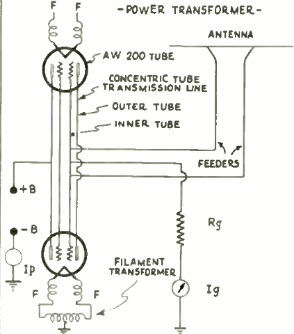
However, cooking with radio energy was not a new idea. In 1933, Westinghouse demonstrated cooking foods with a 10 kW 60 MHz transmitter (jump to page 394). According to reports, the device could toast bread in six seconds.  The same equipment could beam power and — reportedly — exposing yourself to the field caused “artificial fever” and an experience like having a cocktail, including a hangover on overindulgence. In fact, doctors would develop radiothermy to heat parts of the body locally, but we don’t suggest spending an hour in the device.

Continue reading “Tech In Plain Sight: Microwave Ovens”

How To Design A Custom Generator Interlock Plate

If you connect a generator to your home’s main electrical panel when the power goes out, you need to make sure the main breaker is shut off. Otherwise, when the power comes back on, you (or the linemen) are going to have a bad time. There are commercial interlock plates which physically prevent the generator and main breakers from being switched on at the same time, but since they tend to be expensive, [HowToLou] decided to make one himself.

The hardest part of this project is designing the template. It needs to be carefully shaped so its resting position prevents the generator’s breaker from being switched on under normal circumstances, but once the main is turned off and out of the way, you should be able to lift it up and have the clearance to flip the lower breaker. Spending some quality time at the breaker box with tape and a few pieces of cardboard is going to be the easiest way of finding the proper shape.

Continue reading “How To Design A Custom Generator Interlock Plate”

Disinfect PPE On The Cheap With This Hardware Store UV-C Cabinet

The current situation has given closet germaphobes the world over a chance to get out there and clean the hell out of everything. Some of it may be overdone; we ourselves can cop to a certain excess as we wipe down cans and boxes when returning from a run to the grocery store. But sometimes disinfection is clearly indicated, and having an easy way to kill the bugs on things like face masks can make a big difference by extending the life of something that would normally be disposable. That’s where this quick and easy UV-C germicidal cabinet really shines.

The idea behind [Deeplocal]’s “YouVee” is to be something that can be quickly cobbled together from parts that can be picked up at any big-box home store, thereby limiting the number of trips out. You might even have everything needed already, which would make this a super simple build. The business end is a UV-C germicidal fluorescent lamp, of the kind used in clarifiers for backyard ponds. A fluorescent droplight is modified to accept the lamp by snipping off a bit of plastic, and the lamp is attached to the inside of the lid of a sturdy black plastic tote. The interior of the tote is lined with aluminum tape and a stand for items to be disinfected is made from a paint roller screen. The clever bit is the safety interlock; to prevent exposure to UV, the lamp needs to be unplugged before removing the lid. Check out the full build tutorial for details.

We can’t vouch for YouVee’s germicidal efficacy, but it seems like a solid design. If you have doubts, you could always measure the UV-C flux easily, or you could build a smaller version of this peroxide vapor PPE sterilizer, just to be sure.

Continue reading “Disinfect PPE On The Cheap With This Hardware Store UV-C Cabinet”

Low Tech High Safety And The NYC Subway System

The year is 1894. You are designing a train system for a large city. Your boss informs you that the mayor’s office wants assurances that trains can’t have wrecks. The system will start small, but it is going to get big and complex over time with tracks crossing and switching. Remember, it is 1894, so computing and wireless tech are barely science fiction at this point. The answer — at least for the New York City subway system — is a clever system of signals and interlocks that make great use of the technology of the day. Bernard S. Greenberg does a great job of describing the system in great detail.

The subway began operation in 1904, well over 30 years since the above-ground trains began running. A clever system of signals and the tracks themselves worked together with some mechanical devices to make the subway very safe. Even if you tried to run two trains together, the safety systems would prevent it.

On the face of it, the system is very simple. There are lights that show red, yellow, and green. If you drive, you know what these mean. But what’s really interesting is the scheme used at the time to make them light.

Continue reading “Low Tech High Safety And The NYC Subway System”

Laser Cutter Exhaust Interlock Is Silly, Educational, Useful

If there’s one maker space that has an excess of mad scientist type hackers, it has to be LVL1 in Louisville, KY. They sure do a lot of crazy stuff, like this simple device to defeat the laser cutter smoke monster. Nobody got the memo about the “simple” part. Instead they created a functional, educational and aesthetically pleasing element for the hackerspace.

LVL1 has a large format laser cutter. Laser cutters emit nasty smoke. Said smoke needs to be vented outside. To do so, it needs to pass through a scrubber/filter so the neighbouring Pigs don’t complain. So they installed a larger, better filter. The Pigs are happy, until the filter gets clogged and the smoke monster decides to escape. Next they install a pressure switch which disables the laser when the filter gets clogged. Laser cutters have a myriad of safety interlocks, so quite often, it isn’t apparent which one caused it to trip. Hence, the Laser Cutter Enable Module – LCEM.

The simple part was to install an indicator that lights up when the pressure switch is enabled, and off when not. But when it’s off, it isn’t clear if the pressure switch is off, or the indicator has failed. Simple, just install a bi-color LED – Red for off, Green for On. But then what about color blind folks who cannot tell the two colors apart? So, finally, two LED’s with clearly labelled text marking them as Enabled and Disabled.

A simple (this time for real) circuit was finally agreed upon. The SPDT contacts of the pressure switch drive the LED in an optoisolator. Its output drives a DPDT relay via a transistor. One set of contacts light up the two indicator LED’s and the other set of contacts goes to the laser cutter enable contacts. Of course, the optoisolator is totally redundant and over kill too – it’s input LED shares the same power supply as the output transistor! Remember the missing memo?

It was time to assemble the circuit. This is where the mad scientist dudes got really creative. On one half of a piece of acrylic, the schematic diagram was etched using the laser. This ensures n00bs get some education. And the remaining half had the circuit laid out in old-skool wire wrap fashion. Holes were drilled and connections were drawn (using the laser, of course) for the various components. Parts were inserted, and wires were soldered to make the connections. The result is what they call the PCB/Mounting Plate/Educational Schematic/Acrylic thing. Of course, exposed connections and wires are no good. So they made a sandwich consisting of a flat acrylic base, and a cut out frame in the middle to accommodate the wire connections and joints. All of this to light up an indicator. Because.

Thanks [JAC_101] from LVL1 for sending in this tip.

If you want to read more about LVL1 shenanigans, check out this post about their Rocketry group, or this post when Hackaday visited LVL1.