The month or so after the holidays have always been a great time to pick up some interesting gadgets on steep clearance, but with decorations and lights becoming increasingly complex over the last few years, the “Christmas Clearance” rack is an absolute must see for enterprising hackers. You might just luck out like [ModernHam] and find a couple packs of these dirt cheap wireless light controllers, which can fairly easily be hacked into the start of a home automation system with little more than the Raspberry Pi and a short length of wire.
In the video after the break, [ModernHam] walks the viewer through the start to finish process of commanding these cheap remote plugs. Starting with finding which frequencies the remotes use thanks to the FCC database and ending with using cron to schedule the transmission of control signals from the Pi, his video really is a wealth of information. Even if you don’t have this particular model of remote plug, or don’t necessarily want to setup a home automation system, there’s probably some element of this video that you could still adapt to your own projects.
 The first step of the process is figuring out how the remote is communicating to the plugs. [ModernHam] noticed there was no frequency listed on the devices, but using their FCC IDs he was able to find the relevant information. In the United States, devices like these must have their FCC IDs visible (though they could be behind a battery door) by law, so the searchable database is an invaluable tool to do some basic reconnaissance on a poorly documented gadget.
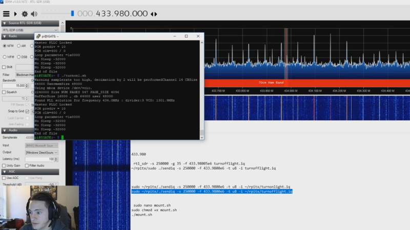
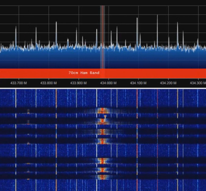
An RTL-SDR receiver is then used to fine tune the information gleaned from the FCC filing. [ModernHam] found that the signals for all four of the remote plugs were being broadcast on the same frequency, which makes controlling them all the easier. Using the rtl-sdr command, he was able to capture the various signals from the transmitter and save them to separate files. Then it’s just a matter of replaying the appropriate file to get the plugs to do your bidding.
Of course, the RTL-SDR can’t transmit so you’ll have to leave your dongle behind for this last step. Luckily all you need to transmit is the rpitx package created by [F5OEO], along with a supported Raspberry Pi and a small length of wire attached to the appropriate GPIO pin. This package contains the tool sendiq which can be used to replay the raw captures made in the previous step. With some scripting, it’s fairly straightforward to automate these transmissions to control the remote plugs however you wish from the Pi.
The RTL-SDR Blog put together their own guide for “brute forcing” simple remote control devices like this as well, and we’ve even seen similar techniques used against automotive key fobs in the past. Amazing what a piece of wire and some clever code can pull off.


This is cool…and an interesting way of approaching the problem. But in the interest of getting other people to use these remote control modules, there is a much easier way. They all (depending on your country) use simple 434 or 315 MHz ASK wireless modules (just search on SparkFun for 434 or 315). You can open one up and read the frequency right off the can.
As far as decoding the protocol, there are some Arduino libraries that may or may not work. I just take a receiver and wire it up to my oscilloscope, and set up a one-shot trigger with a filter for a positive-going pulse after about 50-200ms at low level. The remotes transmit the command packet repeatedly, and the filter lets you trigger on packet start instead of every bit of the packet. Then I just read the code off the screen. It’s usually encoded with swapped ratio pulses (for example, 0 might be 0.3 high and 0.7 low, 1 might be 0.7 high and 0.3 low). But as long as you duplicate the timing in your transmitter, it will work.
Some of the Arduino libraries have a way to watch for and record an incoming code. But for a new pack of wireless switches, my scope method usually takes about 15 minutes to locate and wire up my receiver, capture and write down all the codes, and load into my transmitter (currently an ESP8266 connected to HomeAssistant using MQTT).
If this process was written up it would make a great article
I’d be interested in some more details too. I’m using HomeAssistant, MQTT, and many ESP8266 modules – but haven’t made the jump to RF yet.
A lot of these RF devices use common protocols. I had good luck with pilight identifying all devices at home that transmit at 433MHz even though the brands don’t match at all.
Roman Black has an excellent write up on using the 433 MHz modules: http://www.romanblack.com/RF/cheapRFmodules.htm
Someday I might document this. However, a lot of the concept can be reversed from the rc-switch Arduino library. I don’t use it, but the concept is there. I buy the cheap tx/rx pairs and use them for sampling and transmitting rather than trying to generate a raw 433MHz signal. Warning: a poorly-conceived test of mine once jammed car keyfobs for the whole block.
“Warning: a poorly-conceived test of mine once jammed car keyfobs for the whole block.”
Thank you for admitting that, especially on this forum.
If you want quick control of on/off devices, try OpenMQTTGateway. Its an Arduino/Esp8266 firmware to convert RF/IR/Bluetooth to MQTT and back. It won’t decode data formats (weather stations) for you directly but does dump any RF data to MQTT.
It’s trivially easy to replay that same data back to the RF device.
With those cheap 315/433 modules we’re talking ~AU$4 for the whole thing.
https://github.com/1technophile/OpenMQTTGateway
N.B. not affiliated, just like it.
Hello, OMG can now decode some weather station RF data thanks to the integration of pilight library.
https://community.openmqttgateway.com/t/digoo-dg-r8s-433mhz-battery-operated-temperature-and-humidity-sensor-with-embedded-display/287
Most of them aren’t even full ASK, just OOK. A transmitter and receiver can be had for under $1 and you can drive them with a GPIO.
Is there an advantage over doing the same thing (TX over Pi GPIO) without any additional hardware I have to order on the slow boat from China? Maybe additional range?
seems like making the pi push the buttons would be a lot easier :)
Yup, wire straight to the buttons and just buy an extra remote if you still need it. Remember… K.I.S.S.
On the bench, sure, but any actual application with an appreciable number of lights distributed around the house quickly becomes impractical. This can control lots of lights with a single pin at range.
Are these using anything like the old X-10 signaling over power protocol?
It’s radio, so no. Every one of these cheap RF outlets I’ve seen uses a simple OOK signal on the ISM band with a payload of [(system id)(specific device id)(command)], where each of the id’s are short ints (usually 4 or 8 bits) and the command is a single bit for on or off. *Maybe* Manchester encoded if they care about range. They are extremely trivial to control directly with your own transmitter, but the big downside is that the communication is all one-way only so there is no feedback about the current state of the outlet.
If these things started life as Christmas light controllers I would not use them for anything that I would ever consider counting on. The build quality of most of that stuff is about one notch above bursting into flames. Really, this stuff is not built for near continuous use. They are built to be used one or two seasons than chucked out. As much as I dislike pi’s their build quality is much better. If you can pick up some pi zeros for $5 a pop I would go with them and wifi for the remote end. But that is just me.
Nah I’d grab one of the cheap wifi sockets available these days. Most of them have an ESP8266 inside which can be reflashed (check the reviews to confirm) and are getting below the $9 mark.
What’s going to be doing the switching in this scenario? I’d trust even a cheapo “smart” outlet over just trying to wire the GPIO pins of a Pi Zero to an SSR.
I have done tear downs of several different brands, and all of them I have done so far are based on a 14 pin DIP labeled “AUT980202” for which I have been unable to find ANY documentation. So in 2012 I used a signal analyzer to reverse engineer the signal and the protocol. Now I can control the outlets and/or receive signals from the fobs using an Arduino or other microcontroller. I teamed that up with an infrared sensor and an IR library and now I can control them with my universal infrared remote, trigger at certain times, or in response to certain sensors (such as a PIR)! I documented the AUT980202 protocol in a forum post on the Arduino forum, but that now appears to have been deleted or archived.
https://www.rtl-sdr.com/blind-reverse-engineering-wireless-protocol/
A more fitting title as a response could hardly be url’d together.
Unfortuately the page is very short, but it does provide links to more.
Brilliant!! Thanks for posting this…really a cool solution to a problem I’ve been trying to solve