When we get a new device these days, somewhere in the package is likely to be a wall-wart USB power supply. We look for a place to plug in the little switch-mode dongle, rearrange a few plugs in the mains power strip, and curse its designers for the overly cozy outlet spacing. And all the while that USB-A plug on the power supply cable taunts us with its neat, compact form factor. If only there were a USB power strip.
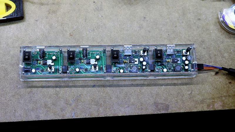
Unwilling to suffer such indignity any longer, [Scott M. Baker] took matters into his own hands and designed this USB power distribution system. We were surprised to hear that he was unable to find a commercial USB power strip, but even if he had, it likely wouldn’t have had the bells and whistles that he added to his. The circuit went through a couple of revs, but each was focused on protection of the connected USB devices. He included both overcurrent protection, in the form of an electronic fuse built around a TPS2421 hot-swap controller, and overvoltage protection using a crowbar circuit with the usual zener-SCR arrangement. There’s also a transient voltage suppression diode to keep any inductive spikes at bay. Interestingly, each USB outlet has all these protections – it’s not just one protected bus feeding a bunch of USB outlets in parallel, but individual modules with all the circuitry. The modules are gangable and live inside a laser-cut acrylic case. The video below shows the design and build process in some detail.
We have to say that we always learn a lot about circuit design from [Scott]’s projects. You may recall his custom Atari 2600 controller or his dual-port memory retro game console, both interesting and instructive builds in their own right.


I’m an old transmitter guy. We didn’t throw a real crowbar across the high voltage. We used an electronic crowbar, like a thyratron, triggered spark gap, or ignitron. You need to sense anomalies in fractions of a millisecond.
Making sure a capacitor is discharged, you can use a screwdriver for. Or a “Jesus stick”, a grounding stick with a hook on the end and a wire to hook up to ground. Best to have a resistor(100 watt or bigger) on the lead so it just goes zaaaap instead of BANG!!!!!!!!!!!!!!.
Non Sequitur. The energy levels are Class 2 per UL1310, or Class I per IEC62368-1 for USB 2; and probably IEC62368-1 Class 2 for USB 3.
The basic design looks good. The only thing it needs is a TVS array on the USB data lines for ESD protection. The PCB layout needs a little works if you want to use some USB data rates, and needs to more carefully route the return paths.
Anker makes a perfectly serviceable 10-port USB charger. I have one on my nightstand and even saw it on sale recently for a measly $18 or so. Sure, it doesn’t have per-outlet switches, but how much more convenient is that than simply yanking the cord?
To each their own, but I would have put at least 4 ports per module.
That defeats the point for him.. At the very beginning he said he wanted each plug protected individually. If there’s more than one port on it. You cannot use the electronic fuse. Because each port added would require a current increase. Therefore, even if only one device is plugged into a 4 plug module, that device could draw 4 amps, for example, before tripping. That’s no good
You can use a load switch IC for each USB output to provide current limiting on a per port basis. Then you can regulate one high current rail, with a 2A limit on each output.
https://www.onsemi.com/pub/Collateral/NCP380-D.PDF
If that defeats his point, then his point is faulty. Fuses don’t protect the load device; they protect the power supply and the wiring to the load. If a device is drawing more current than it should, then the device is already broken, or doesn’t have adequate protection from faults in ITS load.
Yes, exactly! A separate supply for each port is a waste of materials, time and electricity. There is no value in that separate “protection”. Different devices take different amounts of current when running nominally. They should each have their own protection, sized appropriately. If not they are fire hazards.
One big supply would be more efficient. Add one fuse sized to the capability of the big supply (with a margin). Put a bypass cap near each usb socket to keep interference at bay.
Of course, if you want to implement more modern fast charging like USB-C or Qualcom’s series of quick charging formats then you will need separate supplies because they might each negotiate a different voltage. That doesn’t apply though when everything is just 5V.
Also, with 5V charging.. most devices expect some resistance between the data lines or a voltage on the data lines, usually provided by a voltage divider (2 resistors) from the power lines. They use this to indicate that the supply is capable of supplying higher current. Otherwise the device will limit itself to 100mA or maybe not even charge at all. It’s bad enough that many modern devices can’t even charge their batteries faster than they discharge while operating. The device can run out of power while plugged in even though the supply is technically capable of providing more current than the device could use!
Unfortunately every manufacturer seems to ignore any standards and comes up with their own versions of what these resistances need to be. That’s why with older, pre USB-C or Qualcom devices using the wrong brand’s charger often meant slow or no charging at all even though it was all just 5V at some fraction of an amp!
There are chips you can get which will cycle through different resistances and voltages on the data lines, measuring power draw from the power lines as it goes in order to pick the one that gives the greatest draw. They are pretty simple, ground, power in/out and data lines for usually two usb ports. If I were building a 5V distribution bar I would put those on each usb port. Otherwise you will likely find that many devices you try to power charge really slowly or not at all!
Actually, I intended to build just such a thing. I was working on the PCB design, learning KiCAD as I went. But now then we had QC Quick Charge and now USB-C. Like I said, they negotiate voltages higher than 5V so separate supplies ARE needed. And looking at the QC datasheets it seemed to take a lot more components than the plain 5V supply did. I assume USB-C is similar. I decided it wasn’t worth it to me. Instead I would recommend one big 12VDC supply, a fuse and a rail full of “cigarette lighter” sockets. Then fill those up with USB-C/QC Quick Charge adapters. Maybe keep that bypass capacitor idea, put on on each socket. Also, at the end of the chain, maybe a DC-DC step-down converter to 5V with two USB sockets and one of those chips I was talking about, just in case some really old devices don’t negotiate well with the new USB-C adapters. Might as well throw a couple power poles on that 12V line too, just in case you ever want to power a 12V item.
Funny timing of this article, I’m currently developing (for the past 4 years) a bench power supply, which will include USB ports, however, I intend to set and monitor with reasonable precision the output voltage and current. In addition to that it will also allow for USB2 data to flow through if required. since it is taking me so long to develop this project, I might consider procrastinating to a USB3 data/power output. however, I don’t really see a need for that right now.
I will publish everything, once the project is complete.
Quote from the original article: “There’s a few other things worth mentioning. The first is the resistors on the data lines at the USB-A connector. Various manufacturers have adopted various hacks for a charger to tell a device how much current it can draw. This set of resistors forms a couple voltage dividers that Apple devices will interpret as indicating a 5 watt charger.”
Spending so much time and engineering prowess into an impressive USB power supply system and then just voltage dividers on the data pins?
I’d recommend the http://www.ti.com/product/TPS2513 or similar chips instead …
Sure, but in the end that TI device is just acting like a voltage divider or resistors across the D lines anyways. If on the fly reconfigurablility was a goal this TI part might make sense.
Remember that this is more a 5v power supply than a legitimate USB charging port.
It automatically changes how it drives the data lines such that the device will draw the max power.
I have seen this going wrong already. I do not know, if it was THIS chip, but for sure some attempt to try this automatic negotiation. It was a 3A mains powered USB charger and a JBL Bluetooth speaker with 5Ah powerbank function draw 1,8A for about a second or two and after that only 499mA.
It took 1,8A continuously on my (>2A) Samsung phone charger and the Samsung phone took 1,8A on this 3A charger. So clearly there was some misunderstanding in the negotiation of high current. The Samsung charger has the data lines shorted together.
I have been looking for the perfect workbench USB hub/charger.
Isolation is the most important thing. The problem is getting high USB speeds for things like Logic Analyzers. I’m hoping the cost of USB 3 optical cables come down in price, so that an entire hub can be isolated. Then if you need isolation between ports, use USB2 plugin isolators.
The other nice thing, would be PD/Quickcharge circuitry. Then you could have PSU options.
Looks like all the USB3 optical products I’m finding still run power down the cable. Crap.
Sounds like the basis for another project: a hydraulically isolated USB cable. At the source end, 5V from the USB-A jack powers an electric pump that pumps insulating oil through a piece of thin piece of flexible tubing, and at the other end, this powers a similar pump and motor that acts as a generator. A second piece of tubing returns the insulating oil.
oil? Steam!
Cut the power wires and provide your own power from both ends? Ain’t nobody giving us power over fiber yet =(
For speed look into GMR isolators from NVE, not sure if they are usable up to usb3 speeds tho. https://www.nve.com/Isolators.php
(No relation to the company, I came across the isolators on a part search and was amazed that the giantomagnetic resistance found another application next to HD read-heads)
Scott has built a quite complex over voltage protection with Zener, SCR, and then TVS diodes on outputs. I think the same robustness could be achieved with just SA5.0A which is a TVS diode that enters reverse breakdown at about 6V.
A nicely executed project but I don’t quite get it. Try searching for IP6505 module. Their small, dirt cheap single output USB dc-dc converters. You get Qc3.0, soft start and quite a few other niceties. Could easily be ganged together on one 12v supply, if your really worried about isolation maybe include a diode for each. Just add a switch or mosfet for individual control. I’ll post a link shortly for anyone struggling to find them in just a minute.
I found them here, but I’m sure there are plenty of other sellers.
https://www.banggood.com/DC-Buck-Module-12V24V-to-QC3_0-Single-USB-Mobile-Charging-Board-p-1310585.html?rmmds=search&cur_warehouse=CN
There are plenty of usb power strips out there. I bought my first from Anker 5 or 6 years ago. Dude didn’t look very hard.
I have been biting my tongue hard on this one. Who uses a crowbar on a switching power supply? I find it ironic that this is added to a usb supply when I suspect the OP has a computer and tv that cost much more and don’t have them in their power supplies. The fusing. Ueg. All but the lowest cost usb supplies have fuses. Oddly enough I have never lost one in a home plug in device. And the diodes for inductive loads. Are you running your refrigerator off of usb?
I did like the laser cut case. I would just buy 6 identical 2 port usb supplies and plug them into a 6 outlet strip and have 6 fully independent charger ports. I believe the OP is jousting at dragons that don’t exist, or are not problematic. And I find it funny all of the feeds on his come from one common supply so you have a single point of failure. Also, as far as safety goes, I will stick with a simple fuse any day of the week.