[VoltLog] got a hold of a prerelease unit of Joulescope — a DC energy analyzer that promises to make it easy to optimize power and energy usage of your electronic designs. You can find his review in the video below. The device is a very fast ammeter and voltmeter. Given that, it is easy to compute energy and, over time, power.
The device is set to retail for about $400 according to a letter in the video, although the website mentions closer to $800. Both of those seem to be a bit much for a piece of specialty gear that is really just a fast analog to digital converter and some software. To be fair, the device can read ranges between 18 microamps to 10 amps with resolutions as low as 1.5 nanoamps on the lower side of the range. Is it worth it? That will depend on your application and your price sensitivity.
The device has banana plugs but is also set up to handle USB devices with some adapters. The front panel is actually a PCB with a connector so that the panel can change for different applications. The software runs on common platforms and offers a voltmeter-style view and an oscilloscope-like view. The lower the current range, the lower the bandwidth, ranging from 15 kHz to 250 kHz. This isn’t a replacement for a scope but is made to measure DC spikes. [VoltLog] points out that you’ll be most interested in the low range readings when a device is in sleep mode, so the lower bandwidth shouldn’t be a big issue.
The working demo uses a test Arduino provided with the instrument for the review. In other words, if you buy one of these, it won’t have the example board with it. You can see events in the software like LED blinks clearly in the resulting traces.
We’ve seen instruments like this built into an ESP8266 design. We’ve also seen people measure tiny currents using fairly simple techniques.


Much cheaper than an N6705A/B/C
“…Given that, it is easy to compute energy and, over time, power.”
Uhhm… Looks like that’s bass ackwards, unless you literally mean energy divided by time = power.
But of course, measured amps * volts = power (at DC, anyway, if you’re being picky), not energy.
I guess, (and I really don’t know A.I. Williams well enough to speak authoritatively about his thought processes)
He might have worded it just to avoid some DC v. AC Power measurement comment war.
Then again, this is Hackaday, so flame wars on semantics, (spelling, phrasing, etc.) are subtly encouraged…
B^)
Their kickstarter campaign is currently ongoing, and they already reached their goal.
Having reviewed the claims and gone through the docs, I can say for sure that the creator knows what he’s doing.
An easy backing choice for me!
No external trigger input? How do you trigger at a specific time? (to know energy consumption of a particular task/loop)
My current setup is a µCurrent with a Picoscope 2204A, with an external trigger from a GPIO.
Cost way less (60+80€), than this very expensive device, but not isolated.
GPI will be added IIRC (see updates)
[Mathieu],
this is the new project you mentioned in email?
I’m not sure what you’re referring to… maybe the mooltipass mini BLE?
From the preliminary user manual:
“The Joulescope contains two (2) general purpose inputs (GPI) and two (2) general purpose outputs
(GPO). These signals enable time-synchronization with the device under test and other external
equipment. The user interface can display GPIs time-synchronized with current, voltage, and power in
the oscilloscope view.
One intended application for the GPIs is to allow the target microcontroller firmware to identify areas of
interest. The microcontroller can toggle bits so that you can easily see the energy consumption in the
marked time windows.”
Sounds good to me. It’s always a good sign to me that there’s a user manual before the kickstarter has finished.
*disclosure – I backed it.
Looks good, I’m currently using an Otii for measuring the power consumption of a battery powered device. It acts as the power supply as well as providing energy logging.
Before that I used a SiLabs Gecko dev board, really cheap. They have a built in energy monitor via the IDE, you can just remove the Silabs micro and use the dev boards header to power your target at a fixed 3V. Had a small offset but seeing the spike widths during different phases of the firmware really helped narrow down functions consuming too much power.
Otii Arc: https://www.qoitech.com/features
Didnt know this tool, thanks for the insight, looks very powerful, with many more feature than Joulescope.
Tried the software on Ubuntu, looks good, but too bad they have a premium software scheme.
Serial logging is definitely a plus
“with many more feature than Joulescope.” I don’t want to argue with this but I suppose some features may matter more than others. Otii claims “a sample rate up to 4 ksps for the range of 1 μA – 5 A.” whereas Joulescope claims “Joulescope measures current and voltage 2 million times per second with 250 kHz bandwidth. This high sampling rate makes the power consumption of interrupt service routines, inrush currents and other short events visible.” and “Down to 1.5 nA resolution”.
I would say this places them in different value segments. Aside from the number specs, how important is it to you that you can look around, drive feature priorities and contribute to your analyser’s software? Check Github for Quoitech (“This organization has no public repositories.”) and Jetperch (6 repos, 5 of which have been updated this year) for an illustration of the difference in the two companies’ characters. I know which one I want to spend money with.
we need something like the INA219 but able to work with uA, not mA.. :-)
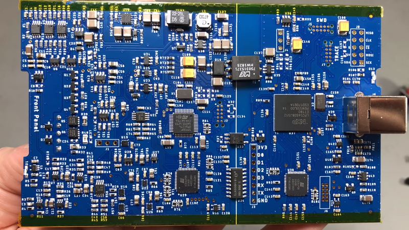
TL/DR This gave me bad vibes and I needed a little rant to get it off my chest.
There is isolation on the board between the sensor and the USB side that is completely defeated by the aluminium case and the tape is tearing… There is a capable ARM controller and an FPGA which do nothing but feed data to USB. There seems to be little or no proper isolation between power to the sensor section and the analogue parts. With a claimed 1 GOhm input impedance I would want isolation. In the video there is a large gap between upper and lower bounds of input and I wonder how much of this is the noise of the units own power supply on it’s inputs.
“When the GPI feature is activated, the voltage and current samples will only be 13 bits (the GPI will be in
the LSB), not the full 14-bits.” – Userguide
The device has 2 CPUs and 2 FPGAs but the protocol is so restricted that you lose ADC precision when you use GPIO. That’s an awful design trade off.
“As the current changes, the ammeter selects the optimal shunt resistor value. ” – Userguide
“The shunt value selection uses the ADC output, dedicated over-range comparators, and a unique
algorithm that runs in an FPGA.” – Userguide
This “precision” instrument uses a propitiatory algorithm to get 32 bits of dynamic range from a 14bit ADC and the software displays these values at high frequency to 5 decimal places. We can’t audit the unit and the designer is bigging up NIST traceable calibration as a possibility. There are no details of the analogue circuits anywhere, no tests to see if they are stable over a range of temperatures or if the circuits are tricked by certain current draw patterns.
Matt is clearly a capable engineer, but he appears to have no track record in metrology. This device seems like it might do the job of showing when a product being developed is using power and giving some insight how to reduce it. So would an oscilloscope and a shunt, voltage sensing in tandem is of little value if your power supply works properly – it maintains constant voltage. Nothing though suggests this is 800 dollars (that’s the RRP, 500 dollars currently on Kickstarter) worth of trustworthy reliable test equipment.
Hi AMA,
[disclosure, I am the creator of Joulescope]
Good to hear you are passionate about accurate energy measurement, something we share!
With regards to the electrical isolation, good eye! The production units fix this issue (no one wants Kapton tape on their pretty board). The design now maintains a 1 mm clearance between the enclosure and the sensor side. The electrical isolation makes Joulescope easy to use (no need to worry about ground loops) and dramatically helps noise performance. Joulescope advertises ±48V isolation, and the Joulescope User’s Guide contains more information.
I think your second comment on isolation is not about electrical (galvanic) isolation but about separation such as guard rings on the PCB. They are there on the areas that matter ;) The board is also washed at manufacturing to remove all flux to achieve the high input impedance. The design has extremely low ripple (as you would expect) on all the power supply rails to reduce coupling. The noise performance is great, and something that the Joulescope User’s Guide needs to include.
On the remainder of your comment, I need to expand the Joulescope User’s Guide to explain how to validate the Joulescope performance on equipment with NIST traceable calibrations. Quantifying static performance is simple since it is pretty standard for multimeters. Quantifying the dynamic performance is more difficult due to the dynamic range. I would love to hear about the test setup, equipment, and tests that would be sufficient for you.
We have focused on making the best, most affordable and easy-to-use instrument for empowering engineers, developers, and makers to optimize energy consumption and reduce battery life. We have been quantifying performance along the way using custom equipment to exercise the full dynamic range. I hope that you will follow along as I release more information over the coming months. In the meantime, you can also check out Jack Ganssle’s hands-on review:
http://www.ganssle.com/tem/tem368.html#article4
Kudos to Matt for a sterling example of how a designer or manufacturer should respond to an adversarial comment. Prompt, respectful, calm, factual, and to the point.
+1
@Matt, thanks for taking time to reply here.
If you add GPIO feature, and UART/debug/log (up to 1Mbaud), then I’m in.
I thinks they are the 2 keys features to debugging, when it comes to chunk of code analysis or IRQ.
Battery analyzer / battery life estimate are not nearly as useful.
@Tweepy I will be adding 2 GPI and 2 GPO to the Joulescope design. You can check out Update #2 and Update #5 on the Joulescope Kickstarter page. I will also add UART protocol decoding. This can easily work up to 250 kbaud (2 MSPS with 8x oversampling) in the Joulescope host software on the computer, like most logic analyzer protocol decoding. I will also be figuring out a way for it work with faster baud rates – I typically run my microcontroller debug serial ports at 1 MBaud, so I agree! Options are:
* Allow 1 GPI channel to run at 24 MSPS in place of the voltage channel
* Use the Joulescope UART hardware in the microprocessor to decode and remux (time accuracy < 1 ms)
* Interface to an external UART-USB adapter (time accuracy < 20 ms, typical )
I also plan to integrate Joulescope with other logic analyzers, likely by integrating Joulescope with Sigrok. The Joulescope GPO will allow for accurate time synchronization. If you have any input, let me know. Regardless, Joulescope will have GPI/O and UART decoding & recording!
” … likely by integrating Joulescope with Sigrok.”
I think this is a good move: I was going to ask about it myself. Using Sigrok will hopefully expose Julescope to more users.
I just received a Julescope unit. I still have to “play around” with it to learn all that it can do. My first comment is that it is well made, but I would have preferred ASCII/txt format of the data file. I suspect I can do that with python script but have not gotten that far.
Quality of build seems very good.
Mark Walter
“to optimize energy consumption and reduce battery life” – are you a battery manufacturer? :-)
LOL, doh! How about “extend battery life”?
@Al Williams
“Both of those seem to be a bit much for a piece of specialty gear that is really just a fast analog to digital converter and some software.”
This is a surprisingly ignorant comment for a HaD author.
@Carl Matthews
Thanks for the tips, those are good suggestions. As I’m sure you are aware, the utility of extremely expensive power analyzers with logging is when you’re trying to characterize power consumption on the nA range over long periods of time, like when your IoT product is in deep sleep.
If Joulescope lives up to the claims, It’ll fill that niche nicely.
You guys might want to checkout the new IOT Power Profiler tool from ZSCircutis. The model no is ZS-2102-A and it can perform similar function. However, it uses a single resistor across the range and uses some precision analog techniques to get the range from few uA to 1A. It has an accuracy of better than 1% and samples at 1MSPS. It is available for sale at http://www.anglercircuits.com
[Disclaimer] I am the designer for the ZS-2102-A.
Hey guys,
i was just looking for something like that.
BUT:
There are so several things on that devices i don’t like!
Yes, i checked the joulescope and the ZS-circuits also the Nordic Power Profiler and something called Otii-arc-01.
I try to give the feedback suitable in a nutshell:
Joulescope:
What i really don’t like is the switching between the different ranges, different ranges are ok, but don’t switch the shunt resistors! Why do you implement an isolation between measurement and USB, when the GPIOs for synchronizing are on the USB potential, if you to an insulation -> do it correctly.
Are the trigger inputs already implemented?
Qoitech Otii-arc:
Very low sampling frequencies and also a very low bandwidth! In my opinion it is useless measuring and evaluate IoT current consumption with low power microcontrollers.
Nordic Power Profiler:
When i saw that these guys are also switching the shunt resistors i immediately stopped looking further in that device.
ZS Circuits Power Profiler:
Well done Prajay, in my opinion your device the ZS-2102-A is the most useful out of this list!
I am missing an isolation between USB and measurement but i can also use a standard USB isolator. It’s a pity that the voltage and the current are not sampled simultaneously!
REMARK: I didn’t check the software yet, but i will probably order a ZS circuits for further testing, probably also for a tear-down ;)
Thanks Tom for the comments.
Adding an isolation was considered initially, but that meant a lot of isolators. At least 12 of them. My decision to leave them out, was with the consideration that most of the people would want to measure the current consumption in the final product, which has a battery. Hence in this case, isolation is not needed. For the engineers who use a grounded power supply, they may use a laptop which is disconnected from the main supply during measurements.
The voltage remains mostly constant over few milli-seconds, apart from the sudden drops during high spikes of current. Hence it was decided to leave out another 1Msps ADC and do away with a slower sampling. The battery life estimation is however not impacted by the voltage dip as it recovers shortly after the current spike is gone.
You are most welcome to order the product. We are running a sale offer for our first anniversary. $200 OFF on the $699.
I’m currently working on a power supply, similar to the Otii solution but with 2Msps sampling and dynamic range of 100nA to 1A with 1%+/-100nA accuracy. It would have simultaneous voltage and current sampling and battery emulation. Still in simulation stages. Should be available by 3Q 2020.
I have been working on a solution to the wide dynamic range current measurement problem as well, and developed this product which is approaching Beta… video demo: https://youtu.be/1uI9FvMNZL0
I just want to add some more features of the ZS-2102-A.
It has an input bandwidth of 300KHz for the current measurement.. It has no sparkle codes or missing codes from the ADC and hence the measurement is very precise over time.It works over 2 Quadrants (V+,I+ and V+,I-) and hence can measure negative currents, which is very useful for energy harvesting IOT devices. As with other devices out there, the ZS2102A can sync the current waveform with a GPIO. (A 8 bit port is provided which can be level shifted from 1.5V to 5V)
It sends the data real time to the PC over the USB 2.0 link. .The software can log data continuously for a few hours ( I have tested for 24 hours long cycles) The data is compressed in real time on the PC. For typical IOT device profiles, a 1 hour data can be logged on a 10GB file. And the software is free and runs on Windows. It needs no drivers as it uses an FTDI device and thus ensures good compatibility.
Hi,
Will it measure non linear DC load current ?