The ages-old dream of home automation has never been nearer to reality. Creating an Internet of Things device or even a building-wide collection of networked embedded devices is “easy” thanks to cheap building blocks like the ESP8266 WiFi-enabled microcontroller. Yet for any sizable project, it really helps to have a plan before getting started. But even more importantly, if your plan is subject to change as you work along, it is important to plan for flexibility. Practically, this is going to mean expansion headers and over-the-air (OTA) firmware upgrades are a must.
I’d like to illustrate this using a project I got involved in a few years ago, called BMaC, which grew in complexity and scope practically every month. This had us scrambling to keep up with the changes, while teaching us valuable lessons about how to save time and money by having an adaptable system architecture.
How to Design a Flexible Embedded Ecosystem
A flexible system is one that can adapt to new requirements and incorporate new software and hardware without significant difficulties. Since it’s often impossible to know what the final set of requirements will look like, it’s best to keep options open, just in case they are needed later. Options means features like connectors for expansion modules, a more flexible power supply than strictly necessary, and a convenient means of re-flashing the firmware.
When the project got open-sourced after a number of months, it had expanded from simply collecting temperature data to also monitoring and controling the coffee machines and the air conditioning units with custom hardware, and reacting to logic running on a number of back-end services. With none of this planned beforehand, the development process involved a lot of improvisation and many revisions of the hardware.
As the project is now known, the Building Management and Control (BMaC) system spans sensors for room temperature, air pressure, relative humidity, CO2, motion and soil humidity, with actuator control for valves, coffee machines, Fan Coil Unit (FCU) fans, as well as pumps and similar. While growing the project in scope was not without difficulties, by leaving options open it nevertheless allowed the system to be extended.
The core hardware consists out of ESP8266 microcontrollers (ESP-12E/F modules), which are cheap and plentifully available, while still providing a significant amount of processing power with its single 32-bit core and easy connectivity over WiFi. This allowed us to quickly roll out the hardware and try out iterations without having to run Ethernet cables everywhere.
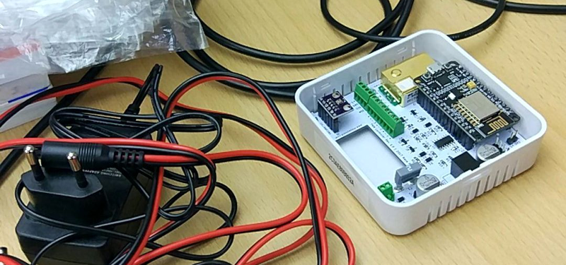
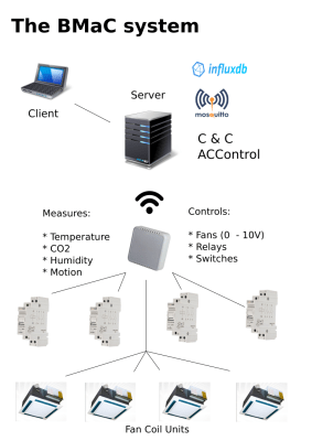
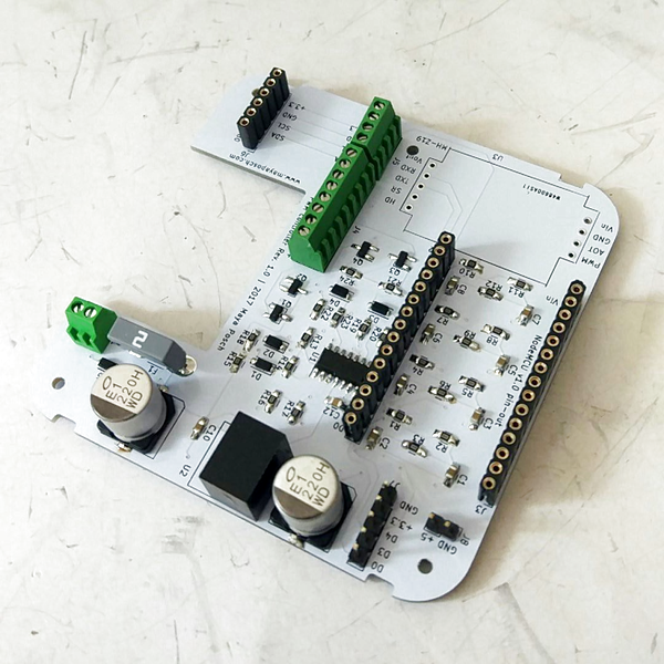
This diagram covers the environmental controls and monitoring, as well as the back-end services, which store the node configuration (Command & Control), provide an MQTT broker (Mosquitto), store sensor data (InfluxDB) and control the FCUs (ACControl). The white enclosure in the center is the ceiling-mounted BMaC node that contains the ESP8266 microcontroller, as well as a custom PCB.
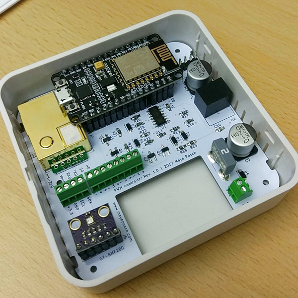
This PCB provides mounting locations for the various environmental sensors, an external I2C GPIO expander, four channels of variable DC voltage output, and power rails for multiple devices running on 3.3 V, 5 V, and 12 V. The cut-out in the PCB is for the motion sensor, which would connect to the free pin header.
And yes, the footprint for the DC-DC module was wrong, which is why the module ended up flipped on the board. The circuit for the DC voltages underwent some debugging as well, as the emitter follower section didn’t allow voltages to go down to zero. These are more examples of a design being rushed through without full validation.
As mentioned, the initial goal was to just put some sensors around the building and store the data that got reported over MQTT. Next the idea to also read out the EEPROM of the coffee machines was added, which required custom hardware to interface with these machines. That escalated into controlling these machines, followed by the idea to monitor motion in meeting rooms, and finally to also control the AC units.
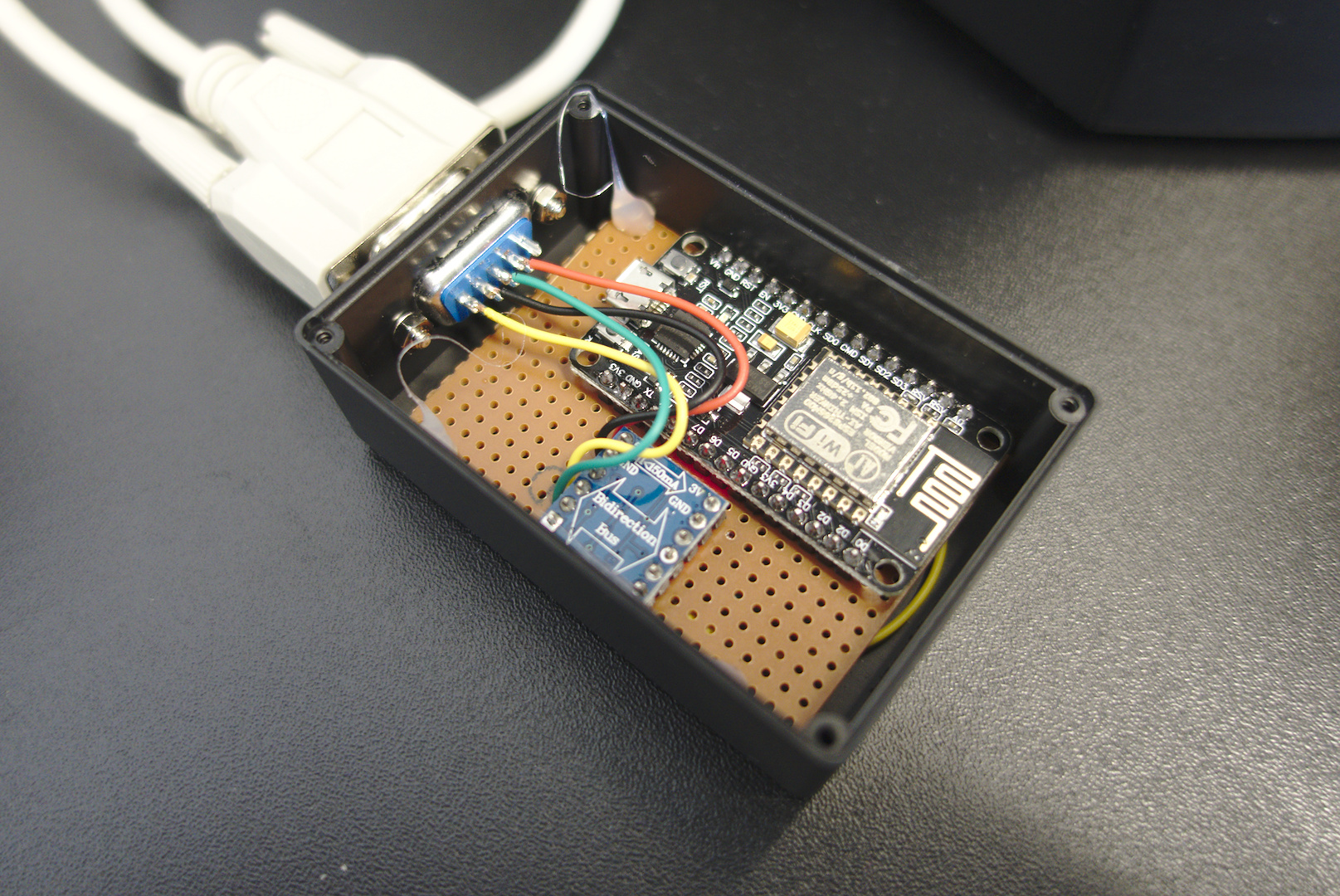 Obviously using the ceiling-mounted node for the coffee machines wouldn’t be very practical, as all that was needed there was a discreet little box that could be put behind the coffee machines, connecting to the serial port on the back of the machine (!), which would also provide the “coffee node” with power via the 5 V line of the TTL serial connection.
All of these nodes then communicated via the same MQTT broker, with the data from sensors being integrated into the backend services. Thanks to the use of MQTT, any MQTT client was able to communicate with any other client, making for a highly flexible network. With the use of WiFi, it meant that nodes could be installed anywhere in the building, with sensors and actuators placed practically at will.
Reverse-Engineering Devices to Control Them
And then came scope creep — the coffee machine controllers would control the building’s air conditioning. While the coffee machine interfacing was a decidedly ‘for the heck of it’ kind of affair, non-functioning air conditioning would be highly disruptive and unpleasant. On the other hand, the original motivation for rebuilding the AC controls was also that the current system did not work properly, with parts of the room freezing while others were sweltering, mostly due to a lack of granular temperature monitoring and control. So there was much room for improvement.
 These requirements meant that we just had to reverse-engineer the entirety of the air conditioning system, figure out a location to mount the new hardware in each room, interface with the air conditioning system, write and expand backend services to support the new functionality, update the firmware on the ESP8266 nodes to do all of the new things, develop custom hardware where needed, and integrate everything into a package that even the average software developer could use in terms of end-user controls.
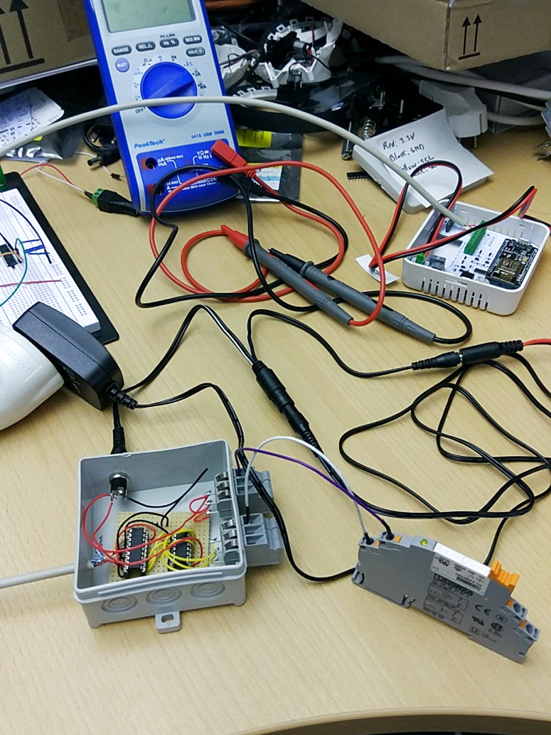
Since the original node PCB could not accommodate all of the valve controls with already four GPIO pins used for the fan controllers of four FCUs, a GPIO expander would be needed for toggling four relays that would control the 24 VAC thermal expansion valves. Here, the I2C breakout header on the node PCB came to the rescue. To control the FCUs, we connected an external PCB that combined an MCP23008 GPIO expander with an ULN2003.
For the switches that toggle the building sections between cooling and heating, another ESP8266-based board had to be developed that would be able to select the desired mode based on commands from the backend. Since we didn’t need to change that often, a latching relay was the perfect solution. It retains the last state even on power loss, and with two sides, the second side could be used as a single-bit memory cell. This led to this beautiful bodge of a prototype.
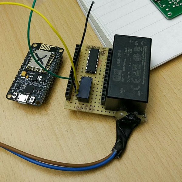
A fun feature of this board is that it directly connects to 230 volt mains power using an AC-DC converter module. The entirety of this board would then get stuffed into the location where the original switch was mounted, with a mains power line being run towards it inside the wall.
The fun part of reverse-engineering like this is that you never really know what you may encounter during the process. If we had first done the reverse-engineering, then made a plan and implemented it, we could have skipped many of the frantic changes and planning. The moral of this section thus obviously has to be that it pays to do the reverse-engineering up front where possible, rather than half-way during the development process. But when that’s not possible, start making break-out boards.
What Worked and What Didn’t
With the hardware more or less finished, it got installed over the course of a few weeks on the first three FCUs and the section’s AC mode switch. Installing the hardware turned out to be complicated and error-prone, with many points where installation could have been simplified. This included things like the screw terminals on the ceiling-mounted PCBs, which are a pain to work with while standing on top of a ladder.
Ideally ceiling-based installations would just involve drilling a hole into the suspended ceiling, leading a cable through it and plugging it into the node before attaching the latter to the ceiling. The less labor one has to perform while installing the hardware, the better. Removing the possibility of switching wires during installation is also highly desirable. This means big, clunky connectors that are easy to install without tools.
During development of the base node board, back when it was a simple temperature monitor, I had decided to have an I2C header on the board, just in case we needed it. This turned out to be a lifesaver. It allowed for the easy extension of this hardware to fully control the FCUs before we even knew how they even worked or what we would need. Having expansion interfaces easily available like that is essential. Plan for the unplanned.
 Sticking to a single hardware design for all nodes, except for the coffee nodes worked out pretty well, as they could be rapidly deployed after finishing the prototyping phase. This let us use a single, unified firmware image, with modules that could be turned on and off for specific functionality. This kept the code base small and organized, and the build- and update process simple, not having to manage which image fit for which node.
The nodes were also configured for over-the-air (OTA) updates, with the rBoot bootloader switching between two ROM slots. This mean that trying out new firmware images was relatively easy, not requiring one to take down the ceiling-based nodes, or fishing the nodes from behind the coffee machines every time an update was available.
Still, trying out new changes was quite involved, with the OTA firmware image having to be pushed to a HTTP server, then the MQTT trigger command sent, followed by checking and validating that the node had properly updated itself and that the changes actually had the expected effect.
The AC control back end was based on the C&C service, with a closed feedback loop implemented for the FCUs and the temperature sensors. With no time left to write anything fancy, a straight-forward loop was used, which then got debugged over the course of weeks, involving countless OTA and backend updates, prodding at hardware while on top of a ladder, and other assorted, muscle-pain inducing fun.
Where to Go From Here
Looking back on the project, it was a good learning experience. If I had to do it again, knowing what I know today, however? There would have been a set of clear goals, with a list of hardware devices to be developed, along with the firmware and backend requirements. I would also have started on the integration test for the software, using a virtual hardware platform and building. The current version of the BMaC platform has since gained exactly this kind of test, which should make any future development much easier. A few years too late for me, but just in time for you!
The BMaC project is still in flux. Hopefully a new opportunity will arise to test out the changes in a new office environment or similar.


Good article, congrats on the project and its success. Did you source that white plastic enclosure?
I was wondering the same. They look like TP-Link router cases without some of the cutouts.
Thank you :)
I sourced the white enclosure, yes. It’s the CamdenBoss CBRS01VWH, with the ventilation slots. There’s also a version without those slots. You can find more information on the PCB and its BOM here: https://github.com/MayaPosch/BMaC/tree/master/esp8266
Excellent, thanks!
I’m curious about the details of the coffee machine control. My coffee machine doesn’t have memory. Can you be a bit more specific as to what the need for control was and what was being controlled?
The environmental control sounds reasonable, I’m just not clear on how/why coffee machines (you must have a lot of them) got added to the list…
These coffee machines are probably worthy of their own article. Basically they are those big, clunky machines that can grind beans, make espresso, add foamed-up milk and such, all automatically. They all use the same electronics inside from Toptronics, which come with a so-called ‘service port’ on the back, which accepts a range of commands.
Using these commands one can read out the EEPROM, write parts of it, erase the EEPROM (bad idea), engage every single actuator or valve in the machine and so much more. It’s a wonderful toy to play with, even if you don’t drink coffee :)
You had me at espresso + UART.
OK, cool, thanks! I think we have one of those at work, too. But why the need for remote control? Or is it more like: “Machine in Conf Room C is out of beans”?
The remote control was mostly as an easy override for the preconfigured ‘products’. Each type of coffee, espresso, etc. is just a collection of commands and durations to the internal mechanisms, from the grinding mechanism to the heater and so on. With the remote control one could for example create one’s own recipe for the perfect coffee instead of relying on things like the ‘strength’ and ‘mL’ settings on the machine.
It’d also allow one to calibrate the machine, as we noticed that the indicated mL ratings across four different of these Jura coffee makers were wildly off. I guess this is a long-winded way to say that the provided firmware isn’t that impressive considering the price tag of the machine :)
I’d love to see an article about those!
I’m honestly surprised that sonoff or some other similar org hasn’t put out an ESP8266 based multi sensor… (or if they have that I haven’t come across it)
I’m waiting on my parts to get here and I’ll be putting a bunch together for my house to go with some existing sonoff (and similar) devices, as well as a smart thermostat, and home assistant.
The “Sonoff SC” exists. I’ve not got one myself as I tend to use Wemosses all over the place.
If you aren’t familiar, check out the Tasmota firmware. The Github wiki is a trove of information. :)
Wemosses?
Wemosii?
Wemii?
M’weem Bway
M’weem Bway
M’weem Bway
In the jungle, the mighty jungle, the Lion sleeps tonight!
B^)
Now that was funny
Thanks for the heads up on the SC, I was unaware of it’s existance… but for the price I’ll stick with my home brewed sensors.
I’ve got dozen+ devices with tasmota on them and the new sensors will likely run it as well..
eventually I’d like to get some of the sensors on battery power, (due to their placement) and that’s going to require deep sleep functionality that tasmota doesn’t presently seem to have… It might be easier to patch it in rather than build something from scratch… we’ll see when I get to that point.
all good points i’m sure but the photos really highlight the best thing in an embedded project: a decent enclosure! i can’t tell you how many things i’ve made using hot melt glue-bound layered cardboard cut-outs, or a cut up piece of a cup with a skewer through it, or just hanging out naked with hot melt glue optimistically splattered over the contacts so it might not short out to its environment before it’s outlived its use. so much hot melt glue. i don’t know about this enclosure but i tell you, my projects have gotten so much easier to work with since i got a 3d printer. a real revolution.
Sounds worthy of an article. “How to design a proper enclosure”.
Project boxes are certainly in the top three of 3D printing’s killer apps. We probably run one such per month. Maybe per week!
So it’s without sarcasm or malice that I sum it up in a link: https://duckduckgo.com/?q=site%3Ahackaday.com+3d+printed+project+enclosure&ia=web
Which is not to say that Maya’s approach (look for nice enclosures on the market, design the boards to fit) is a bad one. It just requires forethought, or a second revision. I’m too lazy for either of those. :)
Measure to plan, cut to fit, paint to cover!
The problem with 3D printing project boxes is that is is wickedly inefficient and limits the size of the enclosure. What I think is a much nicer approach is using one or more commercial enclosures with 3D printed aspects. You get a solid box or boxes and and a custom front/rear panel, and a much more reasonable printing time.
I’m done a lot of little esp8266 projects and have building a template project over the years that contains all the common ‘stuff’. Feel free to use it, https://github.com/holla2040/ESP8266Template . I just add fauxmoESP3 support so I can Alexa control outputs. Very nice. Thanks for the additional comments to my original comment.
“How to Design a Flexible Embedded Ecosystem”
Flexible, Embedded…
WRT the author, it seems like an oxymoron.
B^)
plot twist – next article is on compliant materials and soft robotics ;)
http://news.brown.edu/articles/2019/03/hydrogel
“The BMaC project is still in flux.”
They do make washable flux, you know?
B^)
Nicely done project. I was interested in the reference to retrofitting control systems to existing devices. I have several less common devices to which I want to add remote control and monitoring in a minimally invasive way. These include a UV water purification system, a salt water pool system and several other devices that are unlikely to have manufacturer support for IOT like remote control anytime soon. I have been working on techniques that mimic their existing local user interfaces but the use of techniques like control multiplexing makes building interfaces difficult. Alternative approaches include using mechanical interfaces for input and sensors for the indicators. This is a bit of a kludge and interpreting 7 segment and lcd displays is difficult. Of course, it is always possible to replace existing controls with new ones but the goal is to be minimally invasive. It would be great if there was a way to build up a library of techniques for interfacing and of solutions for specific devices that could be shared. Maybe this is something that Hackaday could sponsor.
Maya, this is awesome. You are truly living up to your hackkitten nickname! This was a joy to read and sort of the kick in the pants I needed to pick up my own similar project and just “finish it”. Well Done!
What a great read. I’m currently working on my own building control but its 98% modified (hardware and firmware) Sonoffs…i’m really really tempted to use your designs for my first ever homemade pcb…its perfect for my needs…now how much will it cost me to set up for smd work :S
I went with 0805 components (and SOIC, SOT-23-3) so that I could hand-solder everything. With the unoptimised design it took me about an hour to finish populating a board. With the upcoming 2.0 PCB revision it should be a lot easier to solder, however, with a big reduction in clunky through-hole components.
I have been using the ESP8266 for a while now, and the biggest problem for not involving the chip in a product that will eventually sit inside a corporate network is absence of support for PEAP/TLS which most corporate WIFI establishments tend to have. Has anyone got success with getting it to work and authenticate and eventually have wifi access in an environment like that?
The most important sentence in this article is this one: “There would have been a set of clear goals, with a list of hardware devices to be developed, along with the firmware and backend requirements.”
All too often projects fail because requirements are not clear. And engineers are a part of the problem, they do not demand proper product requirements and thus have to base their technical requirements on I-think’s and you-decide’s. I had the best results when I stood up to my boss, told him no and explained why we need requirements. And this takes time, up to 2 weeks to 3 months, depending on complexity. But afterwards you are fast, because you know what you need.
I find this fascinating.
As an ex s/w dev the title looks like linkbait for ‘the evils of premature optimisation’ reply. http://wiki.c2.com/?PrematureOptimization
It is strange but as I learn (slowly, more) about electronics and my simple builds I find myself gravitating back to s/w questions like : How will I debug it? Where will I find the logs? How can I unit-test parts of it?
As in this excellent example, we furthermore have to consider How can I expand it? how will I swap parts out of it?
Two things jump to mind from those software days :
– Do one thing, and do it properly.
– Use a Framework – I don’t know exactly how that translates.
And one thing from recent Industrial IoT texts.
– Just put as many sensors on it as you dare, we just don’t know what the data will throw up.
There are LOTS of design considerations and it can be difficult to identify which apply to a project early on. The “one size fits all” only works if the range of applications is narrow and very well defined. The broader the expected range of uses, then the more likely that a family of models will be required. Even on large projects with dozens or hundreds of engineers, finding the right “mix” is difficult; actually more difficult, as many people have opinions. And, opinions are just that; they are not necessarily “better” ideas.
What designers need to understand is that they are attempting to solve multiple problems simultaneously. Size, power, IO, CPU, communications, plus the less often recognized reliability, environmental, thermal, vibration… As a designer, YOU have to solve all of these. The more you get right in the beginning, the better for you as it becomes much more painful if customers identify the problem and expect you to fix it. So the more effort you put into designing a good system in the beginning, the better for you.
Remember: having 1 unit working on the bench does NOT constitute “done”.