An eggbot is probably the easiest introduction to CNC machines that you could possibly hope for, at least in terms of the physical build. But at the same time, an eggbot can let you get your hands dirty with all of the concepts, firmware, and the toolchain that you’d need to take your CNC game to the next level, whatever that’s going to be. So if you’ve been wanting to make any kind of machine where stepper motors move, cut, trace, display, or simply whirl around, you can get a gentle introduction on the cheap with an eggbot.
Did we mention Easter? It’s apparently this weekend. Seasonal projects are the worst for the procrastinator. If you wait until the 31st to start working on your mega-awesome New Year’s Dropping Laser Ball-o-tron 3000, it’s not going to get done by midnight. Or so I’ve heard. And we’re certainly not helping by posting this tutorial so late in the season. Sorry about that. On the other hand, if you start now, you’ll have the world’s most fine-tuned eggbot for 2020. Procrastinate tomorrow!
I had two main goals with this project: getting it done quickly and getting it done easily. That was my best shot at getting it done at all. Secondary goals included making awesome designs, learning some new software toolchains, and doing the whole thing on the cheap. I succeeded on all counts, and that’s why I’m here encouraging you to build one for yourself.
What is an Eggbot?
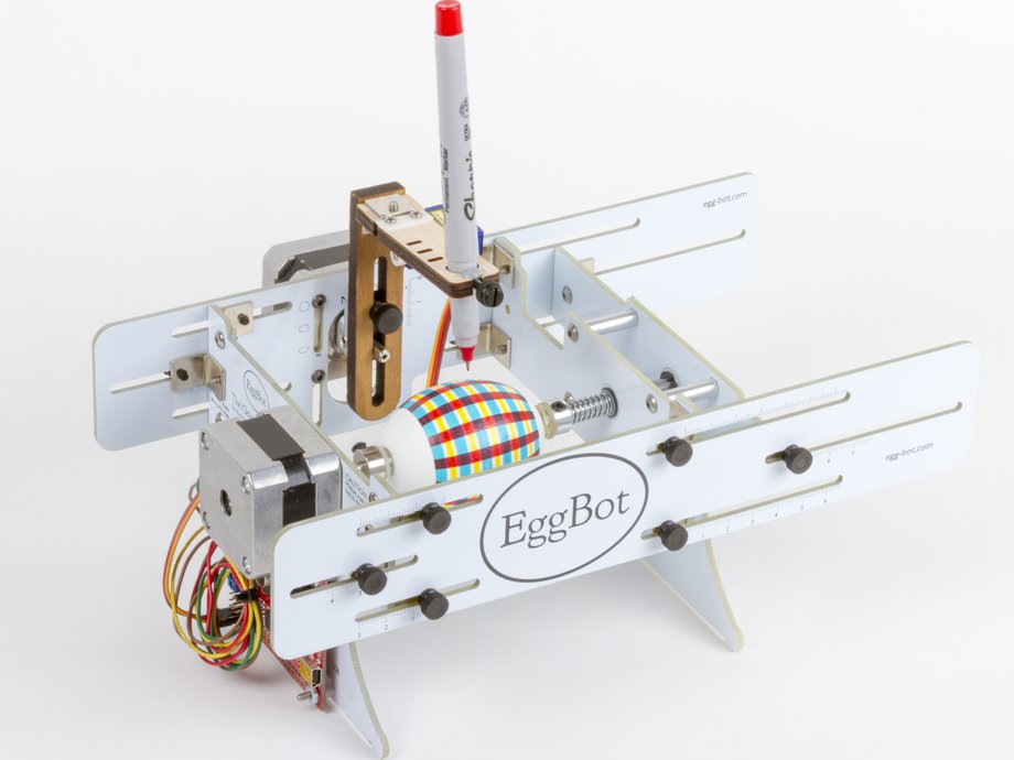
Eggbots first entered my consciousness through Evil Mad Scientist’s EggBot kit. It’s the most refined that we’ve seen, and if you’re making your own machine it’s worth looking at where EMSL include adjustability in their design. But as promised, even a fancy one like this doesn’t have too much going on with the hardware side of things. Your bare-bones version only needs two stepper motors, a micro servo motor to lift the pen, maybe a skateboard bearing and some threaded rod here and there to make it adjustable and smooth. And of course, you’re going to need the electronic bits to drive it all.
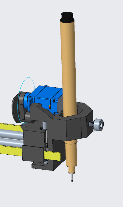
Conceptually, one stepper rotates the egg around its axis of symmetry, the other rotates the pen’s axis so that it can travel north-south, and the servo lifts up the pen between strokes.
For motors, I used what I had on hand, and you probably can too. I bought a big handful of these discount NEMA 17 steppers from a local German supplier, and although they were cheap, they’re probably over-spec for an Eggbot with 0.34 Nm worth of torque. I’ve seen machines that use the ridiculously cheap 28-BYJ48-type gear motors as well, so even those could be made to work. The number of steps is key, and more is better, so you probably don’t want to use any old pancake stepper you find, for fear that you’ll get a low-step variant. For the pen, a servo is a servo, but you want a small one.
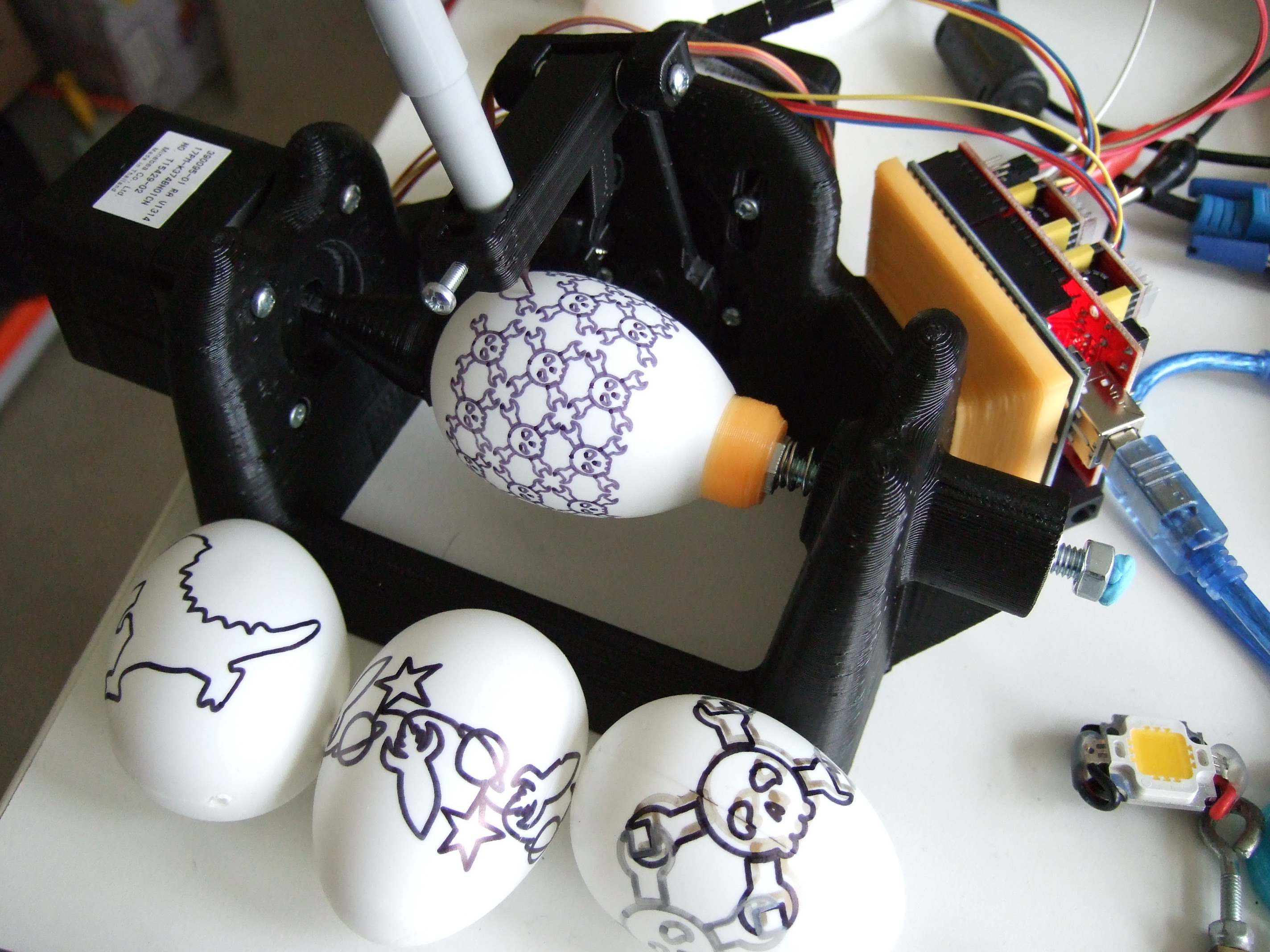
The particular frame I ended up with was a variant of this 3D model but redesigned to print without supports. It’s maybe not as flexible as the original, but tossing someone else’s design at a 3D printer is definitely the low-hassle way to go: download, slice, print, and come back in ten hours. If you’ve got a lot of threaded rod lying around, and want the extra flexibility, I’d consider this battle-tested frame or one of its derivatives.
But even if you don’t have a 3D printer, the mechanics of an eggbot make very light demands on the home builder. All motors are driven directly, so there’s no gearing to worry about. Eggs are light, so you don’t need to sweat about torque. And there’s almost no side-load on the pen tool, so you don’t have to worry particularly about frame rigidity. Have a look at [Zaggo]’s SphereBot made of MDF scraps, or [derwassi]’s CNC Eggbot made of thin plywood for inspiration.
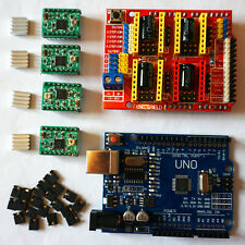 The electronics include two stepper motor drivers and a microcontroller to run the show. I went online to look for Pololu-style A4988 stepper drivers, because I’d used them ages ago in building a 3D printer. I remembered them to cost around $10 each, so I was looking at $20 and a bunch of DIY work. Instead, I found a complete kit with “Arduino”, shield, four (4!) stepper drivers, and even a USB cable thrown in for €15, delivered. Search “arduino grbl cnc shield”, do not collect $200, do not pass Go, and head directly to checkout. Maybe pick up two, because they’re an incredible bargain, and you can’t beat it for development time spent on the electronics side of things. Without the “Arduino” you can get one for €7 and use whatever micro dev board you’ve got sitting around, but you’ll have to do the wiring yourself.
I splurged. After all, minimizing my time and effort spent on the project was the prime directive. Other than soldering compatible headers to my servo motors, everything was plug-and-play. If you haven’t bought oddball servos, you might not even need to warm up the iron. Splurging unfortunately meant waiting, though, and I sat around for a week and a half with a printed and assembled eggbot on my shelf, waiting for electronics, cursing my laziness. Total human time spent on the project, under two hours, and most of that was browsing 3D printed frames online and re-designing some 3D-printed parts to work around my oddball servos. So I guess the waiting pays off.
Wares: Firm- and Soft-
“And the rest is a simple matter of software.” While sourcing all the parts and building the bot took two hours, I spent at least that long looking for the right combination of software and firmware to drive this thing. Learning to use what would become a toolchain took four or five more. I’ll spare you as much of that learning curve as possible.
The plan was to have the eggbot deal in plain-jane G-code because it’s the lingua franca of CNC machines. This is where we part ways with Evil Mad Scientists, because they use a proprietary custom protocol for the EiBotBoard, even if it is open, well-documented, and frankly pretty well thought out. If you just want eggs pronto, that’s a good way to go. But if you want to apply what you learn here to any other CNC machines, from DIY 3D printers to the fanciest of multi-axis industrial milling machines, you’re going to want to deal in G-code. I needed an ATmega328 G-code interpreter.
 Since the dirt-cheap motor-driver board I’d bought was designed to run with GRBL, that was an easy choice. As a bonus, all of my 3D printers use Marlin, so I got to learn something new. The only catch is that GRBL wants to exclusively drive stepper motors, and we have a servo in the mix. There have actually been a number of hacks to GRBL to enable the CNC spindle-speed command to control the servo position, which would be useful if I needed accurate position control, but for the eggbot, simple up-down control will suffice, and it’s nicer conceptually to tie that to the Z-axis height. Hackaday friend, buildlog.net founder, and all around good guy for things CNC [Bart Dring] had just such a firmware hacked together already.
To build up Bart’s firmware yourself, you can download the latest GRBL, then download Bart’s modifications and copy them over the original files. Or just download this repository where I already did that for you. You will want to change the PEN_SERVO_DOWN and PEN_SERVO_UP lines in spindle_control.c to tweak how far the servo moves for pen up and pen down commands. It’s on a scale of 0-255, and 127 is halfway. After this setting, you’re just a make flash away from installation. Arduino folks, you can also compile it in the Arduino IDE.
With firmware on the machine, it was time to play. Plugged into a computer, the eggbot shows up as a serial port (8N1, 115200 baud) and you can open up any terminal and type G-code at it. It echoes “ok” when it’s ready for a new command, and it appears to queue up a few commands on the “Arduino”. You’re going to need to tweak the firmware configuration in a minute or two, so you might as well get used to talking to the machine. G0 X 3.14 Y 0.50 Z 5 will move all axes in sync, lifting up the pen.
 The final step is getting arbitrary artwork converted into G-code. Perhaps the easiest way is using Inkscape, which comes bundled with a “Gcodetools” extension that will do what you want. It’s what I’m using at the moment just to get things done.
But if you’re going to play around with fancier CNC machines later, you might want to investigate something like PyCAM or dxf2gcode. I enjoyed the former, but it’s way overkill for simple stuff like this. Although our own [Josh Vasquez] swears by dxf2gcode, I couldn’t get it running. Something about GUI library versions. Yuck.
Frankly, this last step in the toolchain is where I’m weakest, so if you’ve got any good CAM solutions that are aimed at simple engraving, let me know in the comments. Ideally, I want something scriptable that I can just pass an SVG file and a scaling, so that graphics to plotting is a one-liner.
You may also want a simple script to send G-code to the eggbot. Here’s the one I’ve been using. Note that controlling the eggbot is as straightforward as writing a line to the serial port and waiting for an “ok” in return to send the next.
Tweaks, Optimizations, and Where the Bodies are Buried
And you’re done! At least on paper. Working with all of the sub-parts of the project is fun, and I learned a lot even though I’ve already had tons of CNC-esque experience through DIY 3D printers. Here’s “everything else”.
Machine configuration and GRBL calibration is probably the first step. GRBL has settings ($100-$130) that define how many steps per millimeter the machine is set up to take in the physical world. Printing on eggs is strange at best. As you move north to south, the radius around the egg changes, so “x-steps per millimeter” changes as you move from top to bottom of the egg. What is constant is that with 200 steps per rotation and 16 microsteps, you have 3,200 steps per rotation. A simple choice here is to set “x-steps/mm” to 1, so that an egg is exactly 3,200 steps wide, which is easy for working with graphics — just set the image width to 3,200 pixels or millimeters.
 The y-axis is another story. Eggs aren’t perfect spheres, so an angular step near the top is slightly different from that in the middle or the bottom. I printed out a bunch of squares and tweaked the “y-steps/mm” until it was about right around the equator. It’s pinched at the top and the bottom, but that’s life. Cartographers haven’t solved this problem with centuries of effort, and the earth is less egg-shaped than what comes out of a chicken anyway. I ended up with 0.7 y-steps/mm.
Compared to the defaults, I have just knocked the steps down by a factor of about 1,000. I needed to scale up the maximum speed and acceleration parameters accordingly to get the motors to move at all. Here are my configs. 20,000 steps/minute is about 6.25 RPM. How fast you want to push it depends on how grippy your egg holders are and how runny your pen is.
Now you can figure out what the total y-axis travel for your eggs are. Mine are around 1,000 pixels with this scaling. The Evil Mad Scientist standard egg seems to be 3,200 x 800 pixels. Now you know what to look for in artwork.
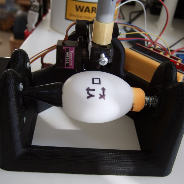
Speaking of egg holders… My steppers don’t have normal 6 mm flatted shafts, so I had to design egg cups myself. The standard solution for holding eggs is to use a little spring tension and the suction cups from kids’ toys. This is not optional — eggs will slip when you change directions if they’re not held in with something sticky. I couldn’t take my son’s toys apart, so I super-glued some old bike inner tube, and the rubber surface seems to grip just fine.
Getting the machine aligned right is important. The egg needs to sit in the cups so that it rotates true. Spin the axis a couple times by hand and adjust until it doesn’t wobble. Because an egg is not a sphere, you will want to lower the center of the y-axis below the center of the egg so that it traces out chords rather than circles relative to the egg, in order to minimize the difference in pen-drop from equator to top or bottom of the egg. Getting the optimal pen height here is also a matter of trial and error (but see orange Sharpie collar above) as is centering the egg north-south. A sample from our fridge suggests that you may want to tweak settings for particularly funny-shaped eggs. I know I’ll never look at a dozen the same way again!
 Finally, if you’re going the Inkscape route, there are a couple things to know about
 Gcodetools that are hard to find out, even if you follow online tutorials. First, you (obviously?) want to be starting with “paths”. If you have an image, use “Path…Trace Bitmap” to get to paths. If you have typed letters or any other native Inkscape objects, “Path…Object to Path”. From there, using Gcodetools is a three-step operation:
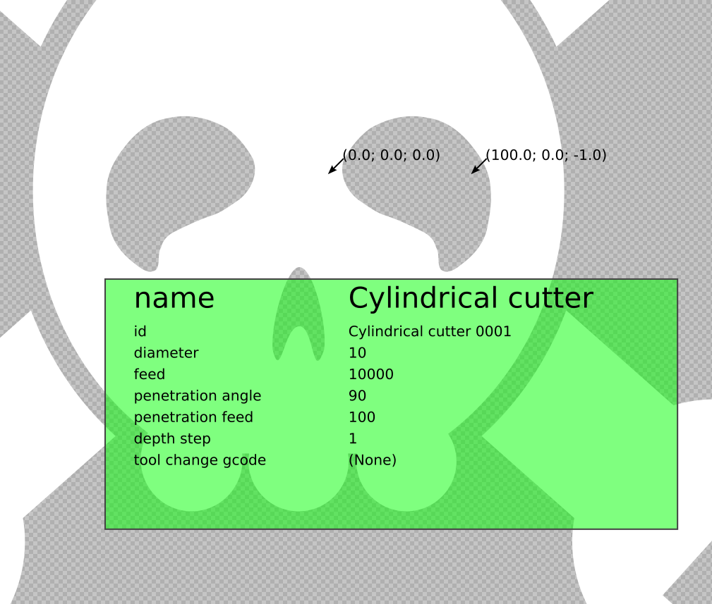
- Select “Extensions…Gcodetools…Orientation points” and hit apply and close. This sets up the G-code origin and scale of your output by superimposing two arrows on the picture. You can move these around to locate the images. I like to put the (0,0) origin in the center of the image. Note that the default width is 1 mm / pixel. It’s not a coincidence that I chose these values for GRBL.
- Select “Extensions…Gcodetools…Tools library”, choose cylinder, hit apply and close. This adds a green box to the drawing, which controls some aspects of the machine speed. We’re pretending to engrave here, and a pen tip is close enough to a cylinder of 10 pixels or steps, so those defaults are OK. You will want to change the feed speed, though. This is how fast it’s going to draw. 10,000 steps / min is about right, but it’ll depend on your pen and your egg. The default of 400 is painfully slow. Edit this value with the text tool (F8).
- Now you’re ready for “Extensions…Gcodetools…Path to Gcode”. In the preferences tab, make sure that there’s a positive value for the “Z safe height”: 1.0 is plenty. Also note where it’s going to output the file. Then click back to the “Path to Gcode” tab (mandatory! counterintuitive!) and click apply.
Build Today, Procrastinate Tomorrow!
An eggbot is a great introduction to the world of CNC. Harder than a pure “hello world”, it’s also a ton more rewarding. You’ve got this.
Building the machine set me back maybe €25, of which only the €15 eBay order wasn’t in my well stocked closet, and took only a couple hours of human time plus ten hours of printer time and two weeks (!) of waiting. I spent much longer selecting the right firmware and looking for the right software toolchain. But much of this time was learning which is never time lost when it’s useful to other projects. Heck, that was part of the point! In the end, Project Eggbot has an exceptionally low drudgery / learning ratio, certainly when scaled by how much my family appreciates funny eggs.
With Easter 2019 just around the corner, however, the eggbot’s days are numbered. I’m still not 100% satisfied with the software side of things, but I can pull down images, convert them to paths and G-code and get them running on an egg in minutes, so good enough. I’ll take any help you’ve got in the comments. I might also swap out the servo for a third small stepper, incidentally un-doing the need for a branch of GRBL. It’s no big deal, really, but I hate the way the pen tip slams down onto the egg when it drops. A controlled landing would be much more elegant.
When Easter is over, the eggbot will fulfill its true destiny as a generic 2.5-degree-of-freedom machine. Once I’ve printed my fill of eggs, I’m unscrewing the motors and the electronics, and I’m stashing the frame in the closet until next year. Then I’m going to have to build another amusing CNC machine. I’m comfortable with the firmware, the toolchain, and the hardware after all. The rest is creativity.
So what’s next? Maybe a wall plotter bot? I love the idea of making the thing wireless, so I’m going to look into Bart Dring’s ESP32 GRBL port. Or maybe I’ll play around with the STM32 GRBL port just for fun. What’s really lacking in any of these machines is a cool, interactive, real-time controller. Maybe I need an etch-a-sketch interface to a wall plotter. Maybe with a balance board and accelerometer. What would you build?
If you think it’s too late for Easter this year, you’re probably right. But an eggbot is awesome on its own, and it’s the quickest first step into generic CNC mayhem. And that’s always in season!


Take a look at bCNC. It’s a pretty complete PC side interface to GRBL and can directly import several file types.
The machinekit variant:
https://www.youtube.com/watch?v=XKCG_Vgj9_k
I too decided to build an egg plotter this Easter. It’s a lot of fun! I ended up designing it from scratch, with a four bar linkage for the pen. Like the featured project, I went the gcode route. I used a ramps board running Marlin and just send servo commands in the gcode thoigh. https://www.thingiverse.com/thing:3564057
That’s awesome. What do you gain (besides it looking hella cool) from the 4-bar linkage?
Why am I asking? I could just Frankenstein yours onto mine and find out…
If you used a stepper for pen control and had a sprung pen holder, you might be able to map the surface of the egg to better match your artwork to the egg shape, and certainly would be able to detect when you’ve touched the surface and stop driving the pen. (I built an extremely crude version of an eggbot out of LEGO back in the early 1980’s and kept jamming pens through the egg shell so I learned about having my tooling spring-loaded.)
It would be interesting to use 3d printed pen holders and use the servo to open/close the pen holding mechanism, so you could have a multicolor plotter with an automatic tool change setup. Hewlett Packard plotters did a remarkably simple job of implementing pen changes that should be pretty easy to replicate with a 3d printed head.
Multicolor pen holder would be fantastic. I’ve tried swapping out pens, but b/c that involves unscrewing them, etc, I always lose registration, and this simple eggbot doesn’t home — zero is wherever you start it.
Even a simple pen-interchange system with human intervention would be better than what I’ve got.
Homing would be cool too.
As for the pen jamming through the surface, simpler is better. In most of the designs I’ve seen, the servo that drives the pen only lifts. When it drops down, it’s free, and the pen just rides on the surface of the egg with its own weight. Works extraordinarily well. Trying to model the egg’s curvature waaaay over-complicates, IMO.
I implemented a simple pen-interchange system in my GRBL-Plotter: https://youtu.be/UvvALanVEEE
I implemented pen changing by trapping M01 (which the gcode generating plugin can insert between layers) in my gcode sender until a newline is entered.
And my firmware also tries to ease the pen down by dividing the pen down move into ten segments over 200 ms. There is also some compliance built into the hardware by coupling the pen arm to the servo with a printed S-shaped “spring”.
What I learned by building an egg bot is that eggs are not symmetrical, and more often than not have odd imperfections that would otherwise go unnoticed when you are using them for their content as opposed to their container. Works great on those plastic ones though.
It’s probably because of the cramped quarters of those stressed hens pumped up for production.
It’s true even of free-range eggs!
Unfortunately, I don’t have data on which hen laid each egg, so I can’t tell you if it’s within- or across-variation. :)
now try some real eggs
I’ve actually drawn on enough real eggs to “appreciate” how different they can be from each other. It’s no biggie, really, but you have to adjust pen height and maybe even recalibrate the y-axis steps/mm if you insist on square squares. Which I don’t. :)
I think a lot of people don’t realize how free this ‘bot is. In the radial direction, you’ve got a fixed angle per step that doesn’t depend on the egg. If you let the pen servo drop far enough, the pen rides on the surface of the egg under its own weight, and picks up a lot of slop / rides over bumps. The only remaining parameter that’s worth calibrating is y-steps. See above about good enough.
The story behind the plastic eggs is that my wife ordered a bag of 500 online a few years ago because it was just as cheap as ordering 20, and we’ve been trying to empty our crawlspace of them ever since.
I’d like to plug my own thing here (https://www.thingiverse.com/thing:844167), which is a derivative of Zaggo’s by way of nglasson. What’s probably of most interest for readers here is the detailed BOM and instructions, with links to firmware targeted for an Arduino Uno with an Adafruit motor shield, but which should be simple enough to retarget to any stepper drivers. Also, instructions for an Inkscape workflow.
Great bot! I looked at this one for inspiration when I was researching mine.
As long as you’re here: how did you do the multiple colors? Just swap out the pens very carefully? I’ve tried a few times with mine, but I can’t ever get things registered exactly right. Maybe I just need practice… or a better pen-holding mechanism.
My firmware obeys the gcode pause that can be inserted by the Unicorn Inkscape extension on layer change. If you use the same type of pen for different colors, the registration is very good. See: https://www.thingiverse.com/thing:953035, also with link to a tutorial on how to do nice area fills.
I must be missing something. I thought Unicorn was long since dead?
Unicorn may be, but their Inkscape plugin works well for generating plotter gcode. I had to make some modifications to that as well, link in the instructions.
I mean, I though it didn’t work with Inkscape versions higher than 0.48.5, and Inkscape is up to 0.92.something last I checked.
It works for me, is all I can tell you. (I accidentally reported your comment when trying to reply to it, sorry.)
Wow, excellent results from that little machine, kudos!
Let’s say you could get a 3D rendering of your particular egg. Or doesn’t have to be an egg, but something else you can spin about an axis and want to doodle on. Is there a software package that supports 3D model -> G code vector generation for lines drawn on arbitrary surfaces?
I wrote some code 6 years ago to solve 2 parts of this problem. The first issue is that eggs are not all the same. Any real egg shape, however, can be modelled very accurately by an equation with two parameters. The second issue is converting coordinates of a 3D curve on a simulated egg surface to the polar coordinates of the Eggbot mechanism. I wrote scripts to do this in Rhino3D. I can draw arbitrary designs in 3D and produce Eggbot ‘toolpaths’, or take Eggbot ‘toolpaths’ and simulate the result in 3D. In the end I spent more time coding (and making a PID controlled kistka attachment) than drawing on eggs, but I can do things that would be otherwise impossible, like drawing a square on an egg that looks perfectly square when looking at the right angle, or drawing straight lines parallel to the longitudinal axis of the egg, or drawing text that maintains the same font size across the egg. See: https://tinyurl.com/y3vyywrz
The problem with drawing squares on eggs, as @BGG points out, is that they only look exactly square from the reference point that you used to make the projection. Turn the egg a bit, and it’s trapezoidal again. This is especially true/problematic as you get closer to the poles.
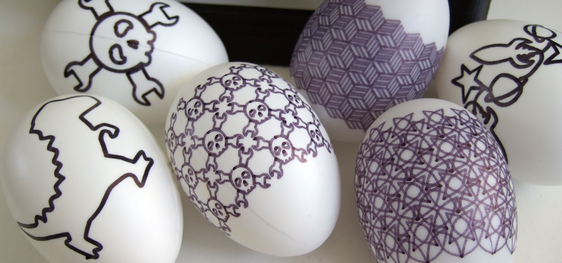
If you look carefully at the 3-row Wrenchers from the equator, for instance, the southern-most ones look too tall. But if you look from the north pole, they’re too short. About the latitude of Boston seems right with the y-steps that I’m running.
This is the cartographer’s problem, and it’s unsolvable. Different projections just make different compromises.
In “user testing” it turns out that people are so stoked to have their name and a dinosaur drawn on an egg, that they’re not particularly worried about the font distortion. We’re all subconsciously used to the effect anyway.
Sure, its all in the eye of the beholder, but the real point is that if you are trying to draw proper pysanky patterns with the Eggbot (i.e. patterns with constant sizes, parallel lines, etc), then you’d better be prepared for some coordinate transforms.
This is a rabbit hole that I’m currently negotiating, for much the same reasons as Elliot. However I’d add at this point- for anybody not familiar with them- that genuine pysanky are prepared by dying in a process not unlike batik, and replicating that using CNC is an interesting challenge.
Could I direct anybody interested at the eBay/Amazon stores of “BestPysanky”, who have the all-important instrument for blowing an egg through a single hole.
Sorry for the revival of an old post. How did you wire in the servo to the CNC shield? I have been working on a similar bot but am struggling with the wiring of the servo. Thanks!
Sorry for the even later reply!
In Bart’s code,he repurposes the spindle speed PWM to drive the servo:
https://github.com/hexagon5un/elliot-s_eggbot/commit/a167f7561ce61db3bd61bdb59f7ace40b9a9c455#diff-3077e7283eb07136d4b755eb5617b4fa11e454392591d8fb7df6ff7e632e6668
So that means servo control pin on PB3 / Arduino Digital Pin 11.
Hope that helps for Easter 2021!
I would also be interested in your wiring diagram. Thanks!
Thanks for the great article! I made a GRBL EggBot with LEGO for the mechanics: https://www.youtube.com/watch?v=zC_oMd-P4vc
More details in the description!
Eggbot is a horrible introduction to the world of anything, except pain. Unless you buy the ready made kit, this is total bs every step of the way. Even this article is full of “well this works, just run this” without proper instructions on how to actually do it. And all the egg/spherebot software is all half-assed, non-functional and abandoned years ago.
Mega GRBL does support the servo out of the box, but you have to apply a patch to the I/O configuration to make it work on Ramps’ servo outputs with 5V, instead of the bed heater. That Uno patch can’t be used directly, so i guess you have to edit the generated g-code to replace the z-axis commands to direct servo commands. No real mechanical explanation anywhere to be found. This is the best example of how a nice idea has been ruined by all around half assering.
How in the world do you think kids can do all the converting and running python scripts and other stuff to just get a damn egg painted, FFS? And that sender script doesn’t work on windows or i’m missing some python module or something, but you know, no instructions. So now again there doesn’t seem to be a reasonable solution to it.
This whole experience has been pretty much the most hostile project ever to try to create something for the kids. Had i known the sorry state of the software, i would’ve not started this.
Elliot, many thanks for the post and detailed description of the project.
How do you think, would it be difficult to port your changes to ESP32 GRBL port? Another idea that came to my mind is that maybe it would be possible to replace servo motor with stepper motor hence Z axis becomes a real axis with a valid height and thus no further patches to GRBL would be required. What do you think?