If you want keyboards, we can get you keyboards. If you want a small keyboard, you might be out of luck. Unless you’re hacking Blackberry keyboards or futzing around with tiny tact switches, there’s no good solution to small, thin, customization keyboards. There’s one option though: silicone keyboards. No one’s done it yet, so I figured I might as well.
Unfortunately, there is no readily available information on the design, construction, or manufacture of custom silicone keypads. There is a little documentation out there, but every factory that does this seems to have copy and pasted the information from each other. Asking a company in China about how to do it is a game of Chinese Whispers. Despite this, I managed to build a custom silicone keypad, and now I’m sharing this information on how to do it with you.
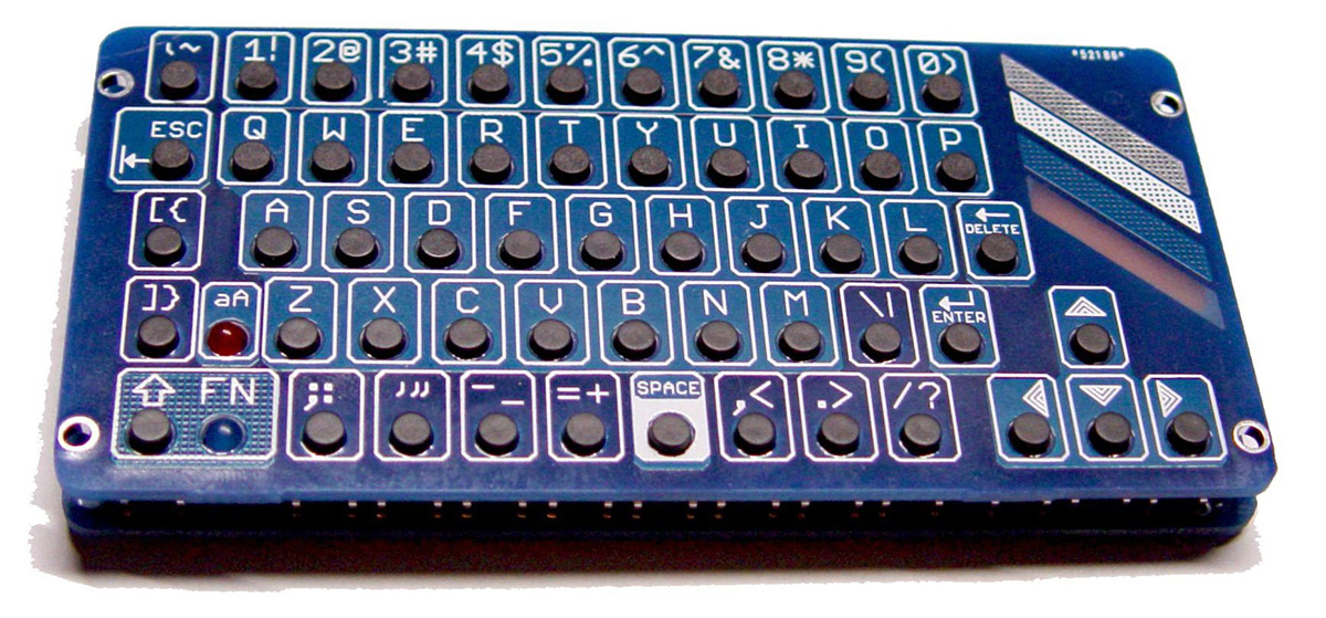
The goal of this project is to build a very small computer keyboard for wearable electronics, electronic conference badges, to play Fortnite on a portable gaming rig, and as a very small USB keyboard. This has been done before. The 2018 Hackaday Belgrade Conference Badge used 55 standard tact switches arranged in a keyboard layout. Another project on Hackaday.io, the mini (Pi)QWERTY USB keyboard, also used several dozen standard tact switches arranged in a keyboard layout for user input. However, there are shortcomings with these devices.
Firstly, standard 4 mm tact switches are fairly expensive. This is not a problem when you’re only using a handful in a project, but if you’re using sixty or seventy switches per device, those costs add up. The cheapest tact switches I have found come in at about $70 USD per reel of 4000, or about two cents per switch. Multiplied by 70, this is $1.25 USD per device, just on switches. It is conceivable that switches could cost more than the microcontroller in a project.
Secondly, tact switches require assembly. The failure rate of a pick and place machine might be very low, but if you’re picking and placing dozens of switches per board, the failure rate will be higher than if there were one monolithic device. Compared to SMD resistors and caps, tact switches are big and chonky, increasing the placement failure rate. Also, since picking and placing switches takes time, you’ll end up paying more for assembling switches versus using one self-contained assembly. This pushes the price of standard tact switches higher.
Finally, and this is purely vanity, tact switches have no labeling. If you’re going to build a keyboard out of 4 mm tact switches, you’ll also need to put labels on the silkscreen of your PCB. The Hackaday Belgrade Conference Badge did this sufficiently well, and the mini (Pi)QWERTY did this spectacularly by using two PCBs, one for the electronics, and another for the labeling. It may very well be possible that tact switch keyboards could be labeled through either screen printing or pad printing, but the surface area is already very small; there’s not much room for labeling anyway.
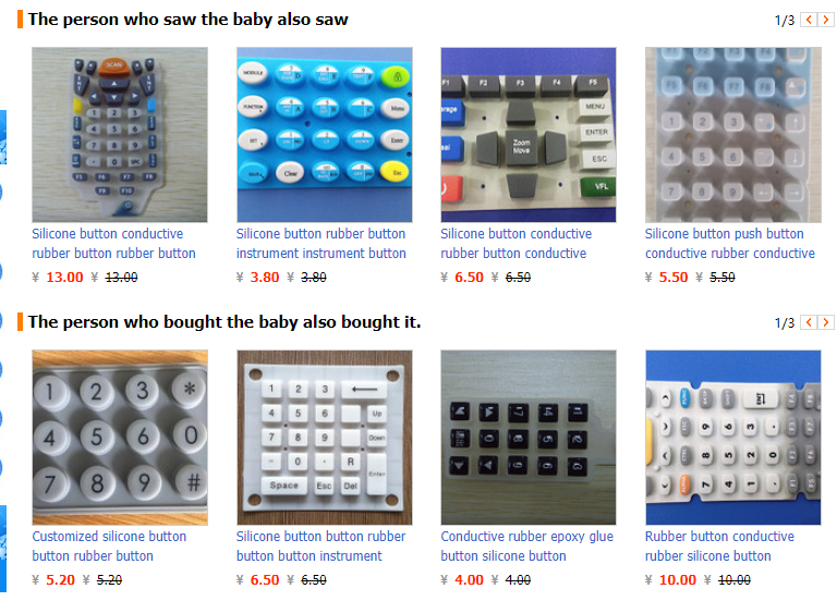
The solution to these problems is using injection molded silicone keypads. You have seen and used these keypads before. They’re found in nearly every remote control I’ve ever seen, they were used in your old Nokia Brick cell phone. Silicone keypads are everywhere, and there are factories that will make you custom silicone keypads:
There are many advantages to using silicone keypads. First, nearly all of them use labeling on the buttons. Second, you are not limited to small 4 mm diameter buttons as you are with tact switches. These buttons can be any size and any shape you can imagine. Assembly is easy; to use a silicone keypad with a printed circuit board, you need only place the keypad onto a PCB; everything else is taken care of. Finally, a silicone keypad simply looks cooler than any array of tact switches ever could. So why aren’t people using them? The reason is mostly cost, but there’s also a fair bit of engineering that goes into silicone keypads.
Different types of silicone and membrane switches
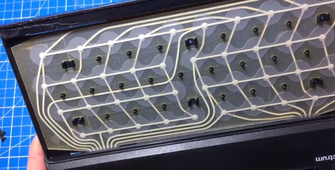
Before digging into the design of silicone keypads, I should discuss the various different designs of small keyboards and keypads. The first is Metal Dome keypads, or membrane keypads. As far as popular home computers of the 1980s, the ZX Spectrum or the Atari 400 (the version with the crappy keyboard) are the best examples of tactile membrane switches. Elsewhere in your home, your microwave probably has one of these keypads.
These keypads arrange buttons in a matrix. The circuit tracing out this matrix consists of conductive ink drawn on two sheets of polyester. A stainless steel dome is placed over each node (under each key) in the keypad matrix. Pushing the button down collapses the dome, making a circuit between the two layers of polyester.
The best pictures you’ll find of a tactile membrane keypad are from one of my projects. Tactile membrane switches do not care how the metal dome is pressed down. The simplest solution to putting buttons and letters on top of the membrane is simply a graphic overlay. A piece of screen printed plastic can be glued down to the array of tactile membrane switches. This is how the keypad in the Speak N Spell and the Big Trak were done. This is how you make a three-year-old-with-Peanut-Butter-proof keyboard.
But purely membrane switches feel cheap, and there’s little tactile feedback for a tactile membrane keypad. One option manufacturers have is to put plastic keycaps above the membrane switch. Take a look at the Metal Dome keyboard again. This is the best visual documentation you’ll ever find on how tactile membrane keyboards are built. They use hard plastic keys to press down on small metal domes sandwiched between two pieces of polyester printed with conductive ink:


Alternatively, tactile membrane keyboards don’t require hard plastic buttons. You can use soft, silicone buttons above a tactile membrane keyboard, like the ZX Spectrum. Instead of hard, plastic squares like my Metal Dome keyboard, the Speccy used a monolithic sheet of silicone buttons. The ZX Spectrum used silicone buttons in its keyboard, but it was still a membrane keyboard. There’s no difference between a metal dome being pressed down by a sheet of screen printed plastic or a silicone square.
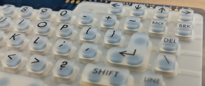
The other type of keypad — and the type I’ve built for this article — is a silicone keyboard, or a ‘chicklet’ keyboard, or to mechanical keyboard enthusiasts, a rubber dome keyboard.
The silicone keyboard uses injection-molded silicone buttons pressing against contacts. In the silicone keyboard, the carbon contact (a ‘pill’) is molded into the silicone button, and the contacts for the keyboard matrix are constructed with traces on a printed circuit board. The contacts can be integrated into the PCB (ENIG gold plating is recommended) or printed on with conductive ink. In either case, the keypad consists of a circuit board, a silicone keypad with conductive contacts underneath each button, little conductive carbon contacts in each button, and a bezel to clamp the silicone to the circuit board.
In deciding between a membrane or silicone keypad, there are a few items to consider, many of which tip the balance in favor of a membrane keypad. While silicone keypads can be made with multiple colors of button, the graphics on a membrane keypad are effectively printed; a membrane keyboard can have any graphic, in any color. Membrane keypads are inherently cheaper, because they don’t need an injection mold. Silicone keyboards require a bezel or fascia to contain the monolithic block of silicone buttons, and this means the added cost of a second mold. Between the two, the only thing a silicone keypad has going for it is the feel. If you’ve ever tried to use an Atari 400, you’ll agree: silicone keyboards are much better to type on. They also have a bit more panache than a membrane switch.
Current research and open projects
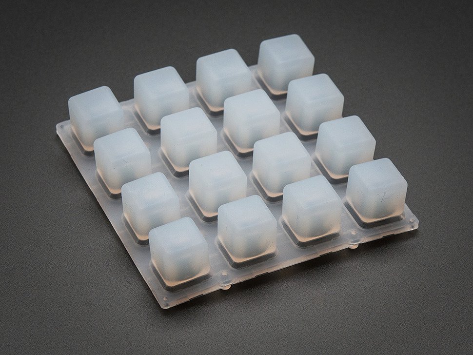
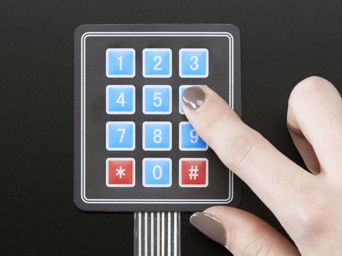
To date, I’m not aware of any low-volume usage of customized silicone keypad. That’s not to say they don’t exist in the DIY community, they very much do: Adafruit sells a 4×4 grid of silicone buttons (Sparkfun has the same thing), and similar silicone buttons can be purchased on AliExpress and eBay. Yes, Sparkfun and Adafruit put some engineering time into the design of the PCBs, but the raw buttons are most likely manufactured in some factory in a far-off land. This isn’t a customized silicone keypad; this is a standard, off-the-shelf keypad used for customized projects.
These specific silicone buttons have been used to great effect, with a Monome clone, a step sequencer, and a MIDI device. This is what a grid of underlit silicone buttons were designed for, after all: they make great MIDI controllers. But because these buttons are unlabeled, they’re not much good for anything else.
These project using 4×4 silicone keypads are, to the best of my knowledge, the only use of silicone buttons in any sort of Maker / DIY / amateur engineering. That’s not to say people aren’t trying. Several people in proper engineering forums are looking at silicone keypads, and a few are experimenting with their own aluminum molds, but to date no one has pulled the trigger. [Dave Jones] has rejected silicone keypads for the uSupply project, instead going with a custom membrane switch.
Design of a silicone keypad, bosses, and fart holes
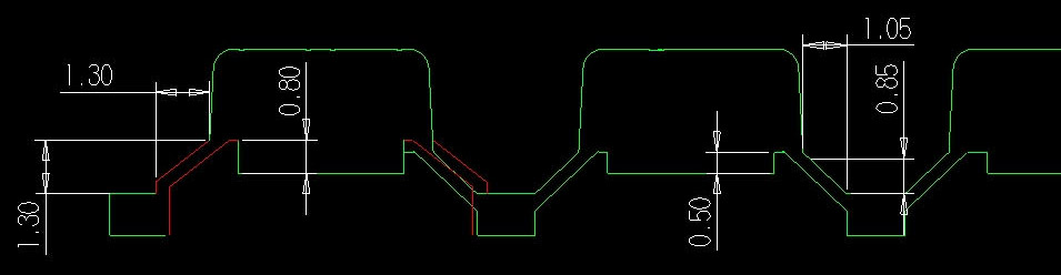
So, what goes into making a silicone keypad? Ultimately, you’re designing a steel or aluminum mold. This mold goes into an injection molding machine where it’s filled with carbon pills, hot silicone is sent in, that silicone is vulcanized, and the part is removed. Further processing can be done to the key cap, such as laser etching the labels, silk screening the labels, and putting a hard epoxy coating onto the key caps. The design of a silicone keypad is the design of an injection mold, but the basic components are actually pretty simple. The example below — a single key silicone keypad — was made in a few minutes with Fusion360.


The outside structure of this key pad is defined by the key itself and a layer of silicone serving as a base. On the corners of this base are four bosses, meant to fit into the PCB. These bosses are for alignment, and so the silicone key pad doesn’t slide around.
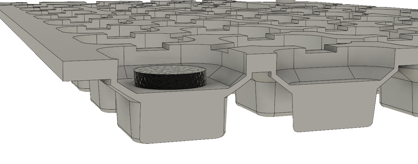
The interior structure of the keypad is defined by a large carbon pill, or the actual contact that will press up against the electrical contacts on the PCB. This is the interior of the key pad I designed, and apart from more keys and more complexity, it’s still the same basic shape as the example above. Notice there are gaps on the underside of the key pad to allow air to pass through to each key. These are fart holes. If you don’t put those in, your keypad will fart.
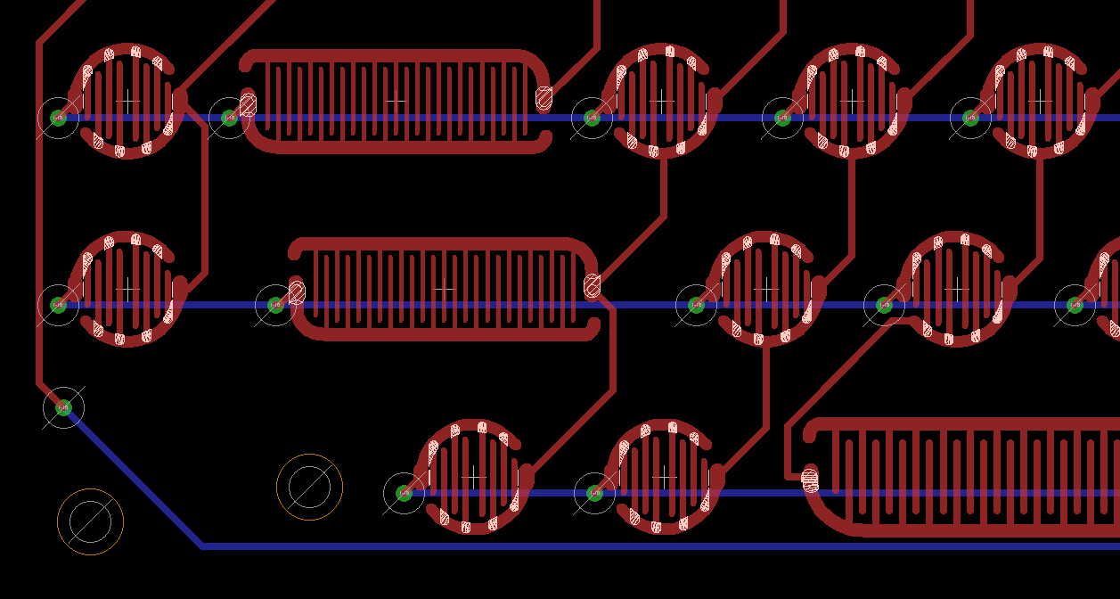 With the design of the keyboard complete and the files sent off to a silicone keypad factory to make a mold and produce a few samples, it was time to create the PCB. In my research, the design of the PCB contacts for a silicone keypad is not critical at all. The only thing that matters is that there are two traces, connected to opposite sides of a keyboard matrix, and these traces should be close together. ENIG, or gold plated finish is recommended. Manufacturing limitations also come into play; the ‘standard’ minimum width of trace and space is 6 or 8 mil, and I designed this PCB with 10 mil trace and space separation for each contact.
With the keypad and PCB done, I could turn my attention to the bezel or fascia. This is a perforated piece of plastic that screws to the PCB. The silicone keypad is sandwiched in between the bezel and PCB. I built this as a prototype, merely to test the keypad as a USB keyboard. The electronics are simply a Teensy LC (because that was what I had sitting around), with a cutout to allow access to the dev board:
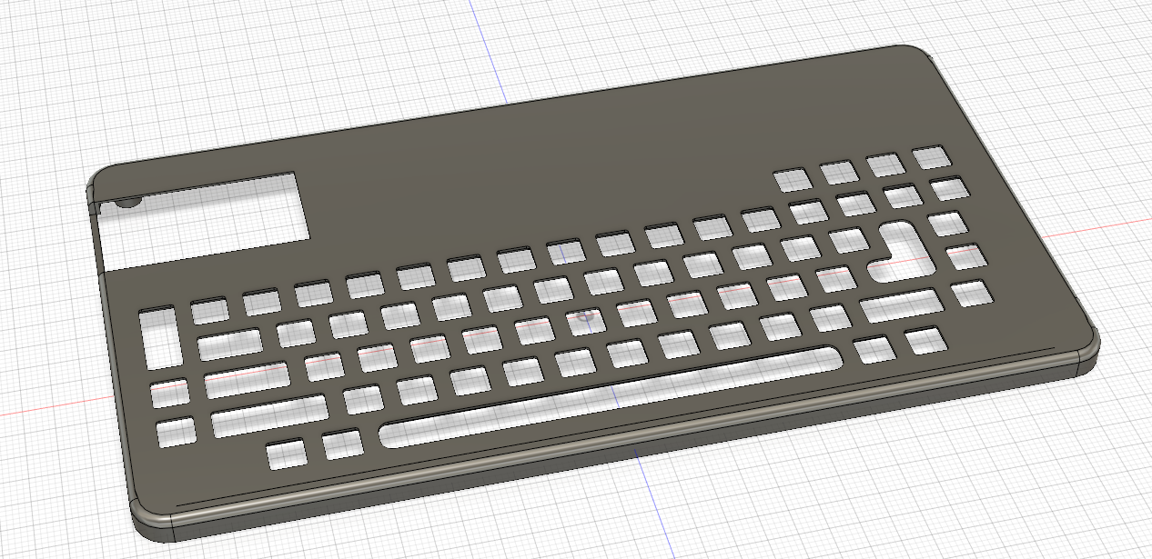
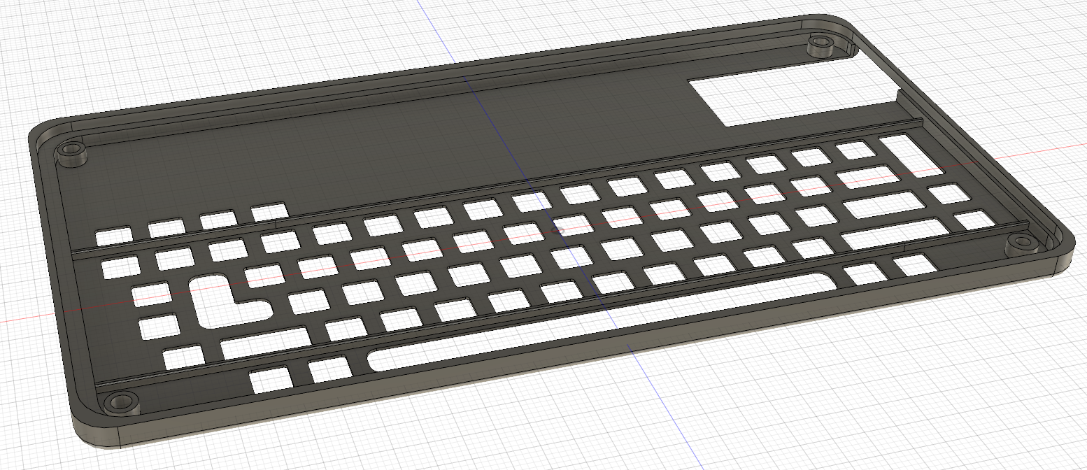
This model was sent off to Shapeways, and the entire thing assembled. The firmware running on the Teensy just uses the standard Keypad library and presents itself to a computer as a USB HID device. This is a custom-made silicone keyboard, in exactly the shape I want it. It’s not the final build, because the USB keyboard is just a proof-of-concept to test the silicone keypad, but it does indeed work.


Economically, this doesn’t make sense unless you’re building 10,000.
I’m going to be completely open with how much this project cost. These prices have a sample size of one; I’ve only talked to one silicone keyboard manufacturer, and I’ve only gotten a quote on one design. However, just because of how competitive the market is, I expect these prices to be representative of the average cost of custom silicone keypads.
The design costs for this silicone keypad are as follows:
| Tooling | $2,219 |
| Design cost | $600 |
| Bank Fee | $58 |
| TOTAL: | $2,877 |
The total cost for a handful of samples is $2,877. This is just the price of the mold and having an engineer look over my CAD files. Three thousand dollars gets me ten keypads.
But once the design and tooling is done, the factory responsible for this can churn out keypads. The quote per piece after this ranges from $1.30 USD for 1,000 units, to $0.79 USD for 5,000 units. So all up, one thousand keyboards will cost me $4,177, or just over $4.18 USD/unit. Five thousand keyboards will cost me $6,827, or $1.36 USD/unit. This last price — under $1.50 per unit — makes this a viable technology for anyone doing small-scale manufacturing.
We know silicone keypads work for large manufacturers; Samsung is selling millions of TVs, and all of them come with the same remote control. The question of making custom silicone keypads for what are effectively DIY project has always been open. There are no small-scale projects that use this technology, and therefore no one to ask if custom silicone switches make sense. I’m here to tell you that it does, provided you’re making a thousand or so units. At around five thousand, the cost of your silicone keypad and associated plastic bezel might be below the cost of your microcontroller.
All the source for this project is available on the GitHub.


Fart holes? Is that the technical term?
“Venting” is the technical term:
The movement of air is called “venting” and is important so that the dome functions properly. Lack of venting can cause adverse affects on the feel and function of the switch. While venting is not absolutely necessary for every application, it is desirable in almost all applications. When the dome is depressed, air is trapped underneath it. To avoid compressing the air under the dome when actuated, it is recommended that a vent channel be present. The venting of the dome can be achieved a number of different ways. Some Examples: a.) vent channel can go from dome to dome via a spacer layer b.) dome arrays can be top vented through the polyester material c.) vent channel can go through the board. Not properly venting the dome will result in significant loss of tactile response.
Trapped air as a form of sensing, and feedback.
Very interesting and extensively researched article. Brian is obviously thinking about something big.
“The person who saw the baby also saw.”
“The person who bought the baby also bought it.”
???
Someone who knows more about Chinese could explain how “product” translates to “baby”
The Chinese word Baobei can have two different meanings: 1. human baby; 2. something that’s good. Apparently the translation is picking the first meaning.
I don’t know anything about Chinese, but both are things that people produce, so it’s not that surprising. In American English, people often refer to things they have made and are proud of, as “my baby”.
That’s google translate on Taobao. Just replace baby with item in your mind and everything makes a lot more sense.
Nahh, you have been rumbled, you were on the Sirius Cybernetics Corporation “Design your own baby” web site. Did you go for the 10% extra limbs free option, or the Zaphod style spare head?
I guess that price point is what’s commonly referred to as “prohibitively expensive” at least for the vast majority of readers who will not churn out anywhere near 10.000 products any time soon… :-(
Can’t imagine it’d be much harder to do with a 3d-printed bit of ninjaflex with the rear pads touched with conductive paint. (e.g. https://www.bareconductive.com/shop/electric-paint-10ml/)
Much cheaper.
And also much less durable and reliable (that paint is not flexible). Oh and you are still missing the keypad labels, which was the entire point of this exercise …
you can print the labels with a different color on a multimaterial printer, you can even add conductive filament to have a one print, keypad! nice!
Looks similar to the the experiences that the wiphone team had in making their own keypad.
for one-offs I think I’d go with the cherry switches off ebay and a 3d printer.
Can different key labels be specified for an already defined silicone moulded keyboard with the manufacturer you are using?
What would be the plan for getting bezels done in bulk?
Hi Expert, would you consider writing a response with corrections and improvements to the article? I am very interested in the subject and I’d love to read more about this, from a semi-hobbyst point of view. Thanks!
I’d love to, but unfortunately these sort of things are semi-trade secrets. I wouldn’t tell just anybody.
Rest assured that I am an expert in this domain, and as an expert I can assure you that nearly everything in this so-called “article” is wrong. Hope that helps.
Rest Assured tham I am an expert in spotting something fishy.
Regardless of the (non-demostrated) experience in the field I would never believe in somebody making big claims and not respalding thems because: “these sort of things are semi-trade secrets. I wouldn’t tell just anybody.”
Silence could have been a lot better, or a few informations, but this self-boasting is deplorable.
no. you are not an expert. YOU are a wanker for not spilling the so called beans on the matter.
Trust me but I can’t tell you anything to prove what I am saying but trust me I am what I say I am because you have to trust me … lol
As to the factual errors in the article, it could be down to how a lot of technical subjects tend to have to be dumbed down to the point of introducing critical inaccuracies so that the general public can have a chance at understanding and staying awake long enough to comprehend what is going on. Also as you mentioned I’m sure in certain situations there’s a lot of secret sauce info and NDAs that could prevent publicly releasing info in the same way you are hesitant to spill what you know. Not an excuse to entirely butcher information, but while you may be an expert in the domain of rubber membranes, you are not likely also an expert in public writing for an electronics hobbyist site (despite voices your strong opinions as such).
“Hope that helps.”
It doesn’t.
We deserve way better trolls than this.
I ain’t gonna buy it without concrete documentation brosef.
Talk shit, get hit, so get elaborating.
I assure you ,you will find the same lack of diligence on pretty much every other article on this site. Especially on Benchoff’s articles. Realize this is a maker community. They are vastly unaware of the real world around them.
How thin is the air up there, so very high on your horse? I guess with selecting a name like TheWizard hubris is to be expected …
I’ll never understand people who look down on others and act like they are so much better.
“They are vastly unaware of the real world around them.”
Maybe he meant himself.
Telling someone they’re all wrong but not pointing out any specifics is peak-crux internet commenting
I find it very humorous that you claim that the vast majority here is ignorant while you’re browsing a website called “HACKADAY” and complain about the quality of the articles. I only wish I was as woke as you :’)
That’s some quality bait right there; perfect 5 out of 7.
TL;DR
Why not simply spend 15-20$ on already build keyboards ?
https://www.amazon.com/s?k=air+mouse&ref=nb_sb_noss_1
Very interesting. Never saw any till somebody gave me a Sony web TV which is gathering dust. Cool remote complete with touchpad and qwerty. Blurtooth doing control not audio, that’s OK.
The worst switches I have ever seen are those metal domes siting under a piece of office tape over the bare copper traces. PRESS HARD!
That worked quite well on a wide range of joysticks for Atari 2600 and other game consoles and computers that had compatible joystick ports.
They worked well for about a week of hard game playing. After that, one of the switches would get flaky and only make contact if you pressed really hard. Then you’d have to fight with your brothers over who got the “good” controller. Until that one started acting flaky as well. Then you’d return the whole thing to the store, get a new system, and repeat the process.
PRESS HARD! Yes. I have a TFA 30.3015 and almost 10 years old. The buttons are the metal type dome and covered with tape. Every year I have to reinstall the 5 stations when I’ve put new batteries in it. After that exercise I have sore fingers, horrible type of switches. Not to mentions the reset combination with 5 buttons.
Remember in the end this will cost them $1.36 USD because they are making in volume. So if they took even the cheapest item on your link (which would also require redesigning firmware and hardware) that would add $12.63 per unit or $12,630 at the end of OPs 1,000 unit run.
Or invest $2500 in something with a return? Ouch.
Just a note for anyone wanting to use the SparkFun or Adafruit keypads – they are slightly different, so don’t expect to get a PCB from one (or use their cad symbols in your pcb) and pad from the other. Adafruit’s is slightly smaller (~60mm^2) and implicitly meant as a 4*4 grid, while SparkFun’s is a larger (~100mm^2) 2*2 grid with score lines to cut into 2*2 or 2*4 grids. They also sell 2*2 sections pre-cut.
Of course a question comes to mind about doing this at home. Wondering if a 3D printer could create upper and lower molds for injection of casting silicone using a calk gun or syringe system. You’d have to source the carbon pills and preload them into the mold.
https://www.instructables.com/id/3D-Printing-for-Two-Part-Silicone-Molds/
Yeah, looks like it could work!
One can also cut the molds with CNC machine, which would make molds smoother. As for carbon pills, one can use conductive carbon spray used for fixing remotes. Or graphite from small battery sliced into “pills” with proper tools.
I’m pretty sure one can buy single silicone buttons too, for fixing remotes and general use. Markings can be painted on using screen printing, CNC plotter or other techniques…
Either 3D printed or cut with a CNC mill, the mold can and should be sanded (and sealed if printed) to achieve a better surface finish. I don’t see any reason you couldn’t get a great surface finish with a printed mold.
> These project using 4×4 silicone keypads are, to the best of my knowledge, the only use of silicone buttons in any sort of Maker / DIY / amateur engineering.
@davedarko has successfully used the gameboy silicone buttons in his projects, and as far as I can tell, the ODROID-GO uses the same.
Yeah the Game Boy Zero posted on Sudomod uses commercial Gameboy (DMG-01) silicone with small volume button PCBs
Interesting article. What about taking this to the next level? Many makerspaces have the tools to machine aluminum molds, so how DIY-able is injection molding silicone?
I imagine [https://www.reddit.com/r/MechanicalKeyboards] probably has more info on all things keyboard.
While we at /r/MechanicalKeyboards certainly have our fair share of knowledge on keyboards, we’d never voluntarily dabble with rubber domes! /s
This article is very interesting, but it made me chuckle when talking about the cost of switches. 2 cents per unit is a bargain considering what enthusiasts pays for mechanical keyboard switches.
Should be pretty easy once you have the mold machined. There’s two part mix-and-pour silicone casting compounds you could use, much like casting polyurethane.
SU&TM$!
I’d like to repurpose a p-touch into a data radio transceiver. Even new these things are cheap. https://www.amazon.com/Brother-PTD210-One-Touch-User-Friendly-Templates/dp/B013DG2FNW/
Yep, the old razor blade marketing scheme.
give away the razor, and make your money on the selling the blades.
But now you can get printing cassettes from AliExpress for much less money than original.
That’s a cool ass keyboard and really what the pocketCHIP needed.
For Raspberry Pi or other USB based keyboard projects, a good source is the HP Slate Notebook detachable keyboard/touchpad (check eBay for 10-P010NR PALMREST KEYBOARD AND TOUCHPAD”. Pop open the back and you will find that the proprietary HP connector routes to a readily available programmable USB Hub IC. You can simply solder a USB cable to the connector pins (black, red, white, green from the left of the connector) and you will have a keyboard with touchpad for your Pi in a really slim format. Perfect for a PiTop.
“The ubiquitous Arduino membrane keypad” Really??? Those were around long before Arduino.
> “The ubiquitous Arduino membrane keypad” Really??? Those were around long before Arduino.
Of course they were, just note that nowadays those 3×4 or 4×4 membrane keypads are often marketed as Arduino accessories on certain Asian websites.
There seem to be quite a few Chinese manufacturers that use the term injection moulding. It seems unfair to say ‘typical rubbish’ when the manufacturer is the one that is potentially providing false information. I’m glad you corrected the article but it could have been done without discrediting the author IMHO.
So, you injection molded the silicone, but 3D printed the housing? Get with the program – this is develop-a-mass-produced-product-a-day. Injection-mold the housing, too. If this was Hackaday, we’d see a description on how to modify an FDM printer to print silicone.
Reading through this I couldn’t help thinking about the common failure of remote
Keypads where one or two buttons stop working due to lack of conductivity. Now if the contacts are a “pill” of carbon/silicon why do they appear to “wear out” / loose their conductivity requiring a coating of conductive part to restore them. I would have thought the rather solid nature of them would allow them to keep working for a much longer time.
For some more info on keyboard design this had some nice pictures and other information https://www.rubber-keypad.com/Carbon-Pills-pl46827.html
Looking forward to completion of your VT-69 project
[https://hackaday.io/project/163829-vt-69-handheld-terminal].
Take my money NOW.
In this video, a fellow does some refurbishment of a Commodore 116 keyboard that is missing some keys. This involves taking a mold of some good keys and using that mold to cast some silicone. he uses conductive pads intended for repairing remote controls for the contact; i have searched amazon and found such things, so they are available.
https://www.youtube.com/watch?v=sufHSRMtk2Q
i am annoyed by these “make your own” slogan.
the desire to make my own keyboard disappear with the time required to source the part.
You can 3D print the flexible part too. There are very nice resins that are very flexible too. I am designing a flexible keyboard using these. https://hackaday.io/project/165186-diy-flexible-keyboard-without-using-silicone
If the keyboard price per unit drops the more you purchase, then how many must you buy to get them for free?!!
Did you make a batch? Can you sell some?
https://www.aliexpress.com/item/100pcs-6-6-4-3-Panel-PCB-Momentary-Tactile-Tact-Push-Button-Micro-Switch-4-Pin/1000007445107.html?spm=2114.search0104.3.101.760f21ccx0m3ea&ws_ab_test=searchweb0_0,searchweb201602_10_10065_10130_10068_10890_10547_319_10546_317_10548_10545_10696_453_10084_454_10083_10618_10307_537_536_10059_10884_10887_321_322_10103,searchweb201603_35,ppcSwitch_0&algo_expid=efffd750-0ba6-47b8-9f6e-7571551f8e1d-15&algo_pvid=efffd750-0ba6-47b8-9f6e-7571551f8e1d&transAbTest=ae803_3
79¢/100, or 0.79¢ each, making that 70key PiMini only 55.3¢ in switches. That seems fairly acceptable for a mini keyboard to me.
Nice to see somebody document the extremes of getting something made. A big investment lots of time and planning. This is an awesome project.
Just out of curiosity – any easy way to make this way, “drum pads” (ex. like the one on boss sp-303)? No velocity or aftertouch needed – just pads with short travel?
I remember when places like Jameco had keyboards of every type imaginable. At one point I was going to add a real keyboard to my ZX-81, but ended up getting a C64
Meh I just use old xbox 360 chat pads. Easy Peezy
Shameless plug of a past project of mine: not sure if anybody else pointed it out, but there’s ways to hack XBOX360’s chatpad (as shown by Ben Heck here: https://youtu.be/Hjdj14C_jAI?t=67 ) which is attractive because in 2019 you can now buy those from GameStop for like $2.