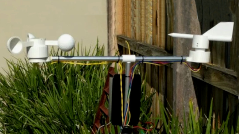
A weather station can be anything from a fun home science exercise, all the way up to a useful tool for planning and weather prediction. [Rob Ward] is one such person who has developed their own weather station, and it recently got a wireless upgrade.
We first featured [Rob]’s work back in 2018, noting that a largely 3D-printed weather station was a particularly useful tool for the home experimenter. The utility of this is now improved, with the addition of a 433 MHz wireless link from the weather sensors back to the base station. Over on Github, [Rob] does a great job of explaining the basics of the Manchester encoding scheme used, and has developed a system that can decode signals from Oregon Scientific weather stations, too.
[Rob] uses the weather station to report weather conditions at Lake Tyers Beach, providing useful information for anyone in the area who might be considering a visit to the coast. It’s not quite as fun as asking whoever’s around on the CB road channel, but it’s a darn sight more accurate for your trouble. Video after the break.


Nice build, but it needs to about 20m higher to avoid turbulence effects from fence (and higher still if within 200m of a roof)
Well clear of sources of turbulence at least.
Thing is, the sources of turbulence cover a much larger area than you might at first think. It’s one reason why wind turbines fixed to gable ends never work well.
The display shows a pressure of 1016 kPa. I guess it’s 1016 hPa.
Yes, I will correct that asap.
The units on the Thingiverse article has mBar which is an equivalent to hPa. I have used an earlier version for the Hackaday release photo, ooops, sorry.
i love it, especially the rain quantifier. but i have one word: ultraviolet radiation.
I agree, however while there are quite a few UV detectors to choose from, mounting them in a weather proof case and still having a low loss UV “window” has been quite a challenge. Any suggestions? There are a few analogue inputs available.
I thought he was thinking about UV destroying the plastic.
I have looked into a UV sensor, and I found quite a few good analogue detectors. However I could not find anything to make a UV transparent window to make the housing weather proof. Any suggestions? The silicon cell was used as a light detector as its spectral response is close to the human eye.
Maybe a piece of a germicidal lamp?
I actually have such a working lamp. However I use it for erasing EPROMs and I think it contains Mercury vapour as well? I was hoping for a plastic?
How does one calibrate a home-made anemometer?
Does it actually turn at the same speed as the wind blows? Or does friction mean it will be somewhat slower. If slower is it by a fixed amount? A percentage? Some non-linear equation? Without already having a calibrated anemometer how can one measure that? (if I had one I wouldn’t be interested in building one) I’ve thought about building one and then calibrating it against the local NOAA report but if the wind is always exactly the same at my location as it is at the airport (where the NOAA station is) then building one myself would be redundant anyway.
I’ve seen plenty of anemometer projects online but none seem to want to talk about this.
From what I have read it is not trivial. Accurate calibration is not just a matter of assuming the tangential speed of the wind, mid cup, is like a wheel on the road and will cause so many rpm depending on radius. Aerodynamics, size and friction are bound to be important. Probably some rule of thumb “gestimate” may be possible, does anyone know of one? Is the rpm to wind speed roughly linear or not?
One dirty way to do it is to take it for a drive. Mount the anemometer on a pole to get it (as far as possible) out of the car’s turbulence. By checking RPM of the anemometer at a series of road speeds, you can make a calibration curve.