[Amon] built an induction heater to break stuck bolts loose. If you work on cars, machines, or anything big and metal, sooner or later you’re going to run into stuck nuts and bolts. Getting them unstuck usually involves penetrating oil, heat from a torch, and cheater bars. Heat usually works well, as heating the bolt makes the metal expand, helping it to break free. Torches aren’t exactly precision instruments though, and things can get interesting using one in tight spaces.
Fire isn’t the only way to heat a bolt through. Electricity can do the job as well. But why use a heating coil when you can grab an induction heater. Mechanics have had induction heaters in their toolboxes now for a few years, under names such as Bolt Buster or Mini Ductor. These devices cost several hundred dollars. However, you can purchase a 1000 watt induction heater from the usual sources for around $30. These are open frame Zero Voltage Switching (ZVS) power supplies, with uninsulated copper coils.
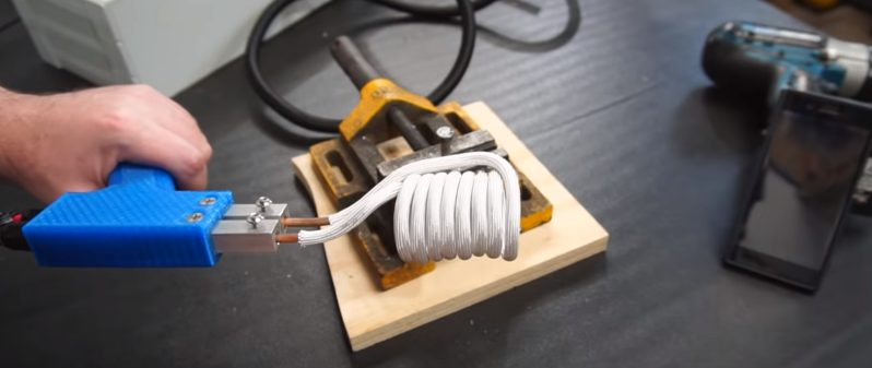
[Amon] bought one of these induction heaters, along with a beefy 24V, 40 amp switch mode supply to power it. He built the two into a plastic enclosure. A relay energizes the induction heater, so it isn’t always running. The key to this build is the handle. Rather than mount the induction coil directly on the supply, [Amon] ran two extension wires to a 3d printed gun style handle. This keeps the bulky part of the heater away from the work. The copper tube coil was re-shaped to better work with the gun. Some fiberglass sleeve keeps everything insulated, even at extreme temperatures.
The result is a very useful heater, ready to bust loose some bolts. We’ve seen homebuilt ZVS supplies powering induction coils before. It will be interesting to see how well these commercial units hold up.


im surprised the inductance of that long cable did not cause any issues
every induction gun i have seen place the power inverter in the (massive) handle
Resistance is futile!.
the cabling used to feed the inductor will add some resistance but is way thicker than the tip.
Naturally the inductor tip will be the first thing to heat up.
The tip does not heat up in an induction heater, it uses magnetic fluxes to induce eddy currents in something within its loop that heats it up
these are typically at a high frequency and current and you typically dont want a lot of inductance on the end of something like that thats not contributing to its action
similar rules apply.
and yes sorry the induced magnetic field melts it.
i mean its not the same rule
Sure, just to clarify… some systems I’ve seen that operate for a longer time interval for casting and forging use copper pipe with a chiller or some kind of coolant system since the induction coil can get hot with prolonged use.
The trick is to (1) use Litz wire that has very low RF resistance, and to keep the conductors parallel like a transmission line.
Take a Weller soldering iron, those with a copper V shaped element, and replace the element with a coil and your done with inductive eating.
Inductive eating?
Is that consuming the food given to recruits at military Induction centers?
B^)
Nah, it’s when Sherlock Holmes is trying to work out where a man has been and he does so by licking some the excrement left by the horse that brought him.
Look at https://www.dictionary.com/browse/inductive:
1. of, relating to, or involving electrical induction or magnetic induction.
English is not my primary language but…
I have a 100 Watt Weller soldering gun, it is too large for most electronics work nowadays, I’d be interested in the gauge of the wire needed, number of turns and diameter and length of the coil.
Rethinking of it, it wouldn’t be efficient because 60 Hertz is a too low frequency.
The soldering gun/iron isn’t an induction system… though wondering if the temperature would be high enough for metal working.
Now, in regards to interesting shapes for foam cuttingm plastic cutting/soldering and even creative tips for IC’s and other shaped components desoldering and maybe soldering… I have seen some neat builds with just plain old residential copper wire shaped as needed.
Weller100/125 watt Iron drive the eating element with 60 hertz current . In the handle there is a step down transformer the secondary is connected to the copper element. Now replace this copper eating element by an open coil, the kind shown on the photo above. Then place some metal rod inside the coil. The rod will eat by induction. This is inductive eating. And the adjective “inductive” is in good use here.
I see what you’re thinking now. Makes sense.
My guess is the pancake coiled type systems are more the mains frequency systems and the smaller number of turn coils aren’t mains and are higher frequency systems. Just thinking like an antenna for the given frequency and like RF burns or not vs mismatched and the antenna heating as best not for these heaters.
I haven’t read into much though and am wondering if I am thinking correct… kind of like an antenna basically thinking is where I’m coming from.
https://en.wikipedia.org/wiki/Induction_heater
“Too large for most electronics work nowadays.”
I use an FM206 now. It’s a maintenance whore, but compared to the Weller transformer-in-the-gun type I started with, it’s nice. I still keep the old Monster laying around, just in case.
*you’re
For a person named [Jacques], English may not be (his) primary language.
It is definitely not my primary language. Although even in french I make many too.
It can be tight when it’s liquid :D
* can’t
Is there a reason that they are not using Litz wire between the active primary coil and the 1000w ZVS induction heater instead of the 3m (10′) insulated 8 gauge copper wire. Solid copper 8 AWG would only have 100% skin depth of 1.63195 mm (0.06425″) at frequencies below 1650Hz (ref: https://www.powerstream.com/Wire_Size.htm ). Is it just for convenience (whatever is at hand), or is just a lot easier to buy 8 AWG copper than 200+ strand type 2 Litz wire.
Is there any advantage to using Litz wire for DC applications like this one, where skin effect is not an issue?
The current through the coils is not DC, it’s high frequency AC, so Litz wire would help but probably not worth the cost since the driver was only ~$30.
Wouldn’t that make it more likely to be worth it???
Being an inductive heater, it’s not using DC to drive the coil.
It’s Marvel not DC.
Even when the skin depth is shallow, thick wire can still be handy. It’s stronger and the added thickness increases heat capacity.
Regarding the inductance of the wire vs the inductance of the coil…
The cable is 1 long, thin single turn
The coil has 8 round turns – and inductance goes with the square of the number of turns
So while the wire could have similar or more inductance than a single turn of the coil, the square term tips the balance and puts most of the inductance in the coil.
I’d have put the whole HF circuit in the gun and had the DC supply feeding it in the cable – thus eliminating this question in the first place. So my solution would have involved less thinking and been uglier.
As can be seen in the video, it works – hats off – awesome!
Those cheap 1000w ZVS induction heaters do indeed have DC on their input and that cable is perfect for there (73 amps maximum for local chassis wiring), 24 to 36 volts for the power in would imply somewhere from 42 to 28 amps for a 1kW power supply.
But the output is high current (could peak at 100+ Amps) AC typically at 30 to 40kHz to induce very high currents (depends on the number of turn on the primary work coil and how small the work piece or secondary is, but it could be 500+ amps) and maximum Eddy currents in the work piece (you could think of work piece, or bolt to be loosened, as a short circuited secondary winding in an air core transformer).
So like I said for the DC part that cable is totally fantastic. But a solid copper cable with an AC signal at 30kHz-40kHz would have skin effect depth of somewhere between 376.4068 μm and 325.9778 μm (0.38 mm to 0.33 mm or 14.8 mils to 12.8 mils). So that 8 AWG (typically rated for 73 amps maximum for local chassis wiring DC or AC below 1650 Hz) has an actual cross sectional area of ~ 8.367 square mm, but at 40kHz due to the skin effect the conduction annulus only has a thickness 0.326 mm which would an equivalent effective circular cross sectional area of only 3.0087 square mm (~1.957 mm diameter). So around 64% higher resistance. This would be roughly equivalent to 13 AWG (typically rated for 8 Amps DC and AC below below 5300 Hz).
Sorry that should be … This would be roughly equivalent to 13 AWG (rated for a maximum of 35 amps for chassis wiring at DC and AC below 5300 Hz). That 8 amps is if 13 AWG is used for longer distance power transmission.
http://hyperphysics.phy-astr.gsu.edu/hbase/electric/skineffect.html
>From the exponential nature of the drop in current density, you can show that 63% of the current will flow within one skin depth δ of the surface and 98% will flow within 4δ of the surface.
Note: 8 AWG: 3.62mm dia Also up to a few skin depth, the wire would still carry some amount of current.
The brute force approach using a large enough wattage and not care about the loss in the cable.
+1 for brute force
Zoro makes a commercial one that works pretty well, but they’re using maybe 3 turns in the coil, and a smaller overall diameter. I really like the remote coil aspect of this build, but I’m wondering why such a huge coil. I can’t think of a scenario where this large a coil is a benefit. Say you have a bolt on an exhaust pipe clamp you’re trying to break loose, it’s going to be much harder to get this one over it.
If you want to see a picture of the Zoro, Google for “Zoro G8712798”
I think the coil choice is purely that it’s the coil that came with the ZVS board: it’s not custom-wound. My experience in playing with this board is that you want the coil-to-work distance to be small, and big mismatches result in the switching frequency going really high and a FET frying.
Funny. You look at it and think “it’s too big”, I looked at it and wondered if it was big enough. Admittedly the last bolts I had issue with were the lugnuts on a 24k pound forklift….
” but I’m wondering why such a huge coil”
Probably because it wasn’t made for bolt loosening, but rather for other applications of induction heating. The smaller coils may not be as readily available on Banggood, etc.
This is certainly a nice build but all of the bolts I have had problems with over the years, thanks to Murphy’s Law, were ALWAYS in very hard to reach places that you could barely get an open end wrench on. There is no way this tool could have accessed any of them. I just did a timing belt on my Toyota a few weeks ago and all the bolts easily reached came right out…the hard to reach ones…not so much.