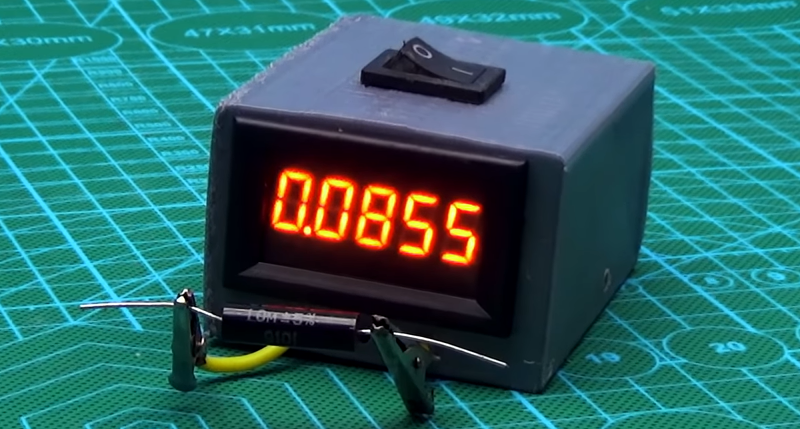
We like to pretend that wires are perfect all the time. For the most part that’s acceptable, but sometimes you really do care about those tiny fractional ohm quantities. Unfortunately though, most meters won’t read very low values. There are tricks you can use to achieve that aim, such as measuring low currents through a device with a known voltage applied. It is handier though to have an instrument to make the reading directly, and [Kasyan TV] did just that with a surprisingly low part count.
The whole thing is built from an LM317, a resistor, and a voltmeter module, that’s it. [Kasyan] mentions the meter’s accuracy means the lower digits are not meaningful, but it looks to us as though there are other sources of error — for example, there’s no way to zero out the probe’s resistance except during the initial calibration.
This isn’t going to be perfect — you’d do better with a 4-wire measurement and a way to zero set shorted probes. However, it does seem to work well enough and it is a simple, but useful, project.
Our favorite quote is this one:
The case itself was printed on a 3D printer. It turned out ugly and not neat, but I don’t care much.
Sounds like a good way to think about it.
We’ve seen homemade meters like this before, but they were more complicated. We’ve even seen them cobbled together which is fine if you don’t care much.


This could be very useful, is very cheap to build, and I have all the parts right now. Great hack!
most such DV-Modules have (solder) jumpers to place the decimal point at will to account for the typical voltage divider at front. Leverage on these to ease the reading!
i have done nearly the exact same thing before same display even, i had an issue with excessive dissipation but nothing a x10 opamp and changing the resistor on the LM337 (its what i had on hand) its extremely reliable and a great textbook design and a great video
i did not even think about documenting it at the time but im glad someone did it has proven an excellent tool and if you can calibrate the current well and the meter its fantastically accurate
Like so many things around us now vs. then, those clips look cheap. I still have some Mueller solid copper alligator clips, those will certainly lower the error. Sometimes I go bananas with the bouncing numbers before some steady perfection state happens and I can believe what I am reading. Dam banana jacks! Cheap plated steel clips, ugh.
A quick search. Oh they invented them. Still in business too. See you later, alligator. After while, crocodile. Both kinds.
Good idea but how spot on is it?. Just get a good multimeter that does the lot. My fluke 289 does all that and more. Just wonder how good it is when it uses cheap Chinese module for the readout plus good milliohm meters cost good money.
No doubt about your Fluke, but that’s kinda not the point.
This article isn’t really for people that already have access to milliohmeters, it’s for those who don’t and can’t justify the cost of buying one.
I dunno, perhaps it is the point. For “access to milliohmeters”, you either have mohm accuracy and repeatability or you do not. LM317-based as either current or voltage sources, at least in my experience, suck. Should have at least used a decent differential amp in lieu of connecting a marginal DPM to a questionable shunt resistor to a
The difference between this circuit and a true mohm-capable circuit is only a few dollars.
My napkin arithmetic indicates, at best, 100mohm accuracy between 20 and 25C; probably worse. So most of those digits have no meaning.
HaD, you’re being lazy. This is poor reporting of a bad hack by someone who doesn’t understand what they’re doing, except maybe in creating videos. This is video clickbait, poorly researched, poorly executed, and apparently made for the sole purpose of gathering views and ad revenue.
And you fell for it.
Al, you *know* the 4-wire (Kelvin) connection is far superior for low-ohm measurement, and you even mention it, but you don’t point out the obvious lack of basic understanding in the source.
All it would take to turn this approach into a FAR better measurement tool is just two more alligator clips (and two more wire leads). That’s it. Two from the current source, two to the voltmeter. Negligible increase in cost. Enormous increase in value, especially as a example to others.
It’s a serious disservice to the community to give this junk airtime. Shame on you.
Even a simply example showing where the error comes from with 2 wires measurement and how/why 4 wires overcome that for low resistance measurement would help a lot of your target readers which falls into the unexperienced category.
At least they didn’t use hot glue…
100% agree. This is completely useless and even worse than that. Anyone who knows anything about measuring resistance knows one needs a 4 terminal probe.
That’s not really fair. Most people don’t have a need for 4-wire resistance measurement. Most people have never seen a 4-wire resistance meter. And I’d wager that a majority of the readership here have never thought about when they might need one.
A huge part of the value of this site and this community is to bring concepts like this to common knowledge. *That’s* why this post failed: it showed an egregiously bad example of how to do something and missed the opportunity to introduce something valuable to the greater readership.
Fair enough. They got me. I’m not often in the camp of needing to do this particular measurement and so it has always come down to minimizing measurement error using whatever I have on hand.
I have this on hand.
Compensating for test lead resistance was just a matter of shorting leads and mental math, but of course no assurance that the measurement is linear or accurate. I imagine that is a good part of what a 4 lead meter ultimately eliminates right?
If you do have something to add here for the readership which would improve this knowledge gap, this is a good time to chime in. No disrespect intended. Just want to know.
You’re absolutely right. Nobody here has actually explained the advantage of 4-wire measurement. So here it is:
There are two ways to measure resistance: 1) apply a known voltage to the resistor and measure the current through it, 2) pass a known current through a resistor and measure the voltage across it. Then divide the voltage by the current to get the resistance. The problem in either case, is that you just want the resistance of the resistor, not the resistor plus the test leads, plus the contact resistance from the test leads to the resistor. Using only two leads, there is NO WAY to cancel out both the lead resistance and the contact resistance. Which is what the device that is the subject of this article mistakenly attempts to do.
Now. In a practical sense, it’s easier to measure voltage than current. In fact, most digital ammeters just measure the voltage across a known resistance. So most digital ohmmeters use method 2, as described above. But if you have an accurate way of measuring current, you could certainly take the first approach. But either way, you need to know both the current and the voltage, accurately.
The four-wire method uses two pairs of leads. The first pair is the source of current. Now, as long as the resistance under test plus the resistance of the test leads is within the range through which the current source can accurately supply a known current, that current will be known. It doesn’t matter what the contact resistance, or the resistance of the test leads is, because the current source supplies a known amount of current.
Now, with a separate pair of test leads, we measure voltage across the resistor. THESE leads carry almost no current – their current is determined by the input resistance of the voltmeter, which can be very high, so the current through these wires is very close to zero. The higher that input resistance is, the less effect the test lead resistance has on the measurement.
So now we have a current path, from the current source, through one set of wires and the resistor under test, whose current is almost completely independent of the resistance of the device under test OR the test leads. And we also have a voltage measurement path, whose indication varies very little with the current through ITS leads. So neither the current nor the voltage measurements are affected by contact resistance or test lead resistance.
High-price milliohmmeters also take temperature into account, but really, this is all we need, if we’re going to do our measurements close to 25degC. If we choose a value for the current source that’s a power of ten, then we can use the voltmeter’s reading DIRECTLY to indicate resistance. If we use a 1 A current source and a 1.999 V digital voltmeter, we directly indicate 0 to 1.999 ohms, because 1.999 V / 1 A = 1.999 ohms. If we use a 1 mA current source and again, a 1.999 V digital voltmeter, we directly indicate 0 to 1999 ohms, using the same formula. We can pick a current range and a voltage range to give us very precise measurements for any range of ohms. But this works ONLY because we separately assure that the current and the voltage are not affected by leads or contacts.
Thanks for writing all that good explanation out, BrightBlueJim. I’m motivated enough to complain, but too lazy to explain. Sorry for that.
Thank you Paul and BrightBlueJim. That was a pretty good explanation for the limited format of a comment.
Constant current sources are valuable beyond LED’s.. who would have thought! (kidding)
Now how do you calibrate that…
Definitely worthy of being included in an article about milliohm meters. Cheers.
Which is why this would have been a good time for the article’s author to explain how 4-wire ohmmeters work, and why they are a good idea. But he totally blew off that opportunity.
Your comment exactly shows why this is a really bad had article. It is a lost opportunity to show readers why you MUST DO 4 terminal measurements in this case. Because had readers may not know…
Hello,
I’m new here and a novice to electronics. Can anybody here provide a schematic to turn this project into a 4 wire kelvin device. I’m just a hobbyist so, this project seems useful to me – I don’t have the means nor the need for a super accurate meter. I just need a plan for modding this simple meter. Please reply. Thank you kindly
“let’s add another 1% for any losses in wires and connections.” Complete wild-ass guess. I would suggest more like 20%, as long as we’re guessing, since there is no accounting for the contact resistance, which will change from measurement to measurement. This is useless.
Looking at the responses here, I’d like to make a contest recommendation:
The Under $5 Resistance Meter Contest!
How good of a resistance meter can you make for under $5? Grade on accuracy, power dissipation, and ease of home construction. How accurate and low power can you go with a design that is easy to hand solder? That would be the winner.
Do we get mass order discount to get to the 5$ mark? Because i’m having a hard time sourcing a 5 digit panel voltmeter for less than 3.2$ right now…
rubypanther: so, is it your opinion that the price is the most important factor? From your specifications, everything else is graded, but the price is an absolute limit. Well, sometimes you get what you pay for, and I’m pretty cheap, but I doubt that anything that can be built for under $5 will be worth even $1. I would be happier with a contest about how cheaply you can produce a meter that can measure 10 mohm to 1 ohm within 5%. For my five bucks (or ten), it’s more important to actually meet a spec.
How much effort are you willing to put into being a cheapskate?
It’s a reasonable assumption that anybody wanting milli-ohm measurements will likely have access to a DC power supply and at least one ordinary voltmeter. In that case, your Resistance Meter is the cost of a single resistor in series with your unknown: measure the voltage across both, and with a little simple arithmetic you can get accuracy and precision limited only by the quality of your own meter, and the accuracy of your test resistor.
It doesn’t even need SIMPLE arithmetic. If you have an accurate 1 mA current source, which you apply through a resistor, you can measure the voltage drop across the resistor WITH SEPARATE LEADS, and the number of millivolts measured will be EXACTLY the number of ohms of the resistor.
Personally I would just go on eBay and buy a used 4 wire ohmmeter for a few bucks. I have a couple meters capable of doing the 4 wire thing and truthfully, I can not recall the last time I used that function. I suspect you are talking in the $25 range for a used one if you are willing to wait for the right unit to come around.
IMHO, and this is just IMHO, about 90% of the stuff you do, you can probably do just fine with a free HF DVM. For that extra 10% of the things, you really do want to get the right tool for the job.
But that’s really not the point. The point, made by Paul above, is that it would take only two more wires and two more alligator clips to make a 4-wire measurement that would be 100 x as useful. You CAN’T take an accurate measurement below 1 ohm with a $5 HF multimeter. But you CAN take an accurate measurement with a current source and a voltmeter, hooked up to four separate wires. NO extra cost.
Question: Isn’t it possible for there to be multiple points, including both Paul’s point, and also my point?
Sure it is. But maybe I don’t know what your point was, then. All I gleaned from your post was that sometimes, the absolute cheapest is what you need. Okay, yes. But Paul’s point was that the additional cost for 4-wire measurement would be very close to zero. I mean, literally two alligator clips and two pieces of wire, for a vast improvement in utility. How much do two alligator clips cost?
I think my Toneohm is the most essential tool I have and you can buy one for not a lot more than the cost of the parts in this (well less than 10X used:)). Without doubt hte most useful thing ever for finding shorts, in particular SM capacitors.
Rather than reply specifically, I’m just going to do a blanket response. There actually is a 4-wire article in the queue which I was writing when this came up (looking for meaningful links). I mentioned it, but didn’t want to turn this piece into that piece. However, as for everyone’s nay saying to the people posting the video — by that standard we should not post Arduino clocks because, after all, there are GPS-disciplined oscillators for not much more and everyone knows the Arduino isn’t that accurate without external help, right? Not everyone is at your experience level with electronics, nor mine. The fact that I have a Fluke meter that will do 4 wire (not that I use that function much) within arm’s reach of me doesn’t mean there isn’t value for someone to build this and what they might learn from doing so.
I’m glad when I was a kid building stuff that was probably amusing to the old timer’s point of view none of them savaged me as being an idiot. Of course, in those days, you had to do it in person and most of us probably wouldn’t be so bold with our opinions face to face.
The last time I used a 4 wire meter was the mid 90’s. I do remember it now, but it was during college, and it has actually been that long since I’ve needed accuracy in that range. The majority of the time I *do* use a HF multimeter, as I have like 5 of them. I destroyed my last ‘good’ meter almost 10 years ago and it has never been replaced as I’ve learned to cope with what I have.
This was a great article about doing just that with acceptable results, and so I appreciated it.
I actually think the internet has had the reverse effect on me in that I’m more likely to say what I think at the moment in RL as well. Sometimes that can be better. Depends on where you started from probably.
That has also ultimately led to me never posting anonymously. I may occasionally remove direct linking when I go a little more off the rails, but never anonymous. When the internet police knock on your door 50 years from now after the Singularity has taken control, you should be prepared to own what you have said. :)
Looking forward to your 4 wire milliohm meter article.
Two from the current source [battery], and connect them to what? And two to the volt meter, from where/what? Sorry for my ignorance, I’m a complete NOOB to electronics but I’m trying to learn and I believe that this device, with the four cable connection modification, might help me locate shorts on PCBs. So, please reply. Any insight will be greatly appreciated. Thank you kindly