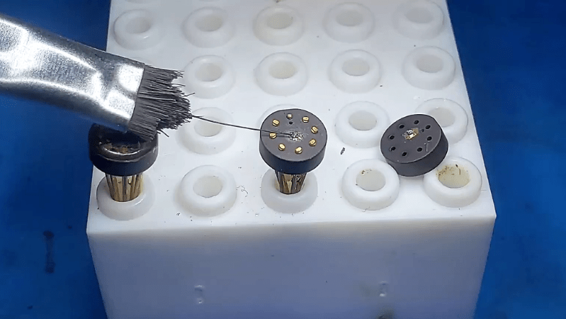
You’d think that something called “white fuming nitric acid” would be more than corrosive enough to dissolve just about anything. Heck, it’s rocket fuel – OK, rocket fuel oxidizer – and even so it still it wasn’t enough to pop the top on this vintage Fairchild μL914 integrated circuit, at least not without special measures.
As [John McMaster], part of the team that analyzed the classic dual 2-input NOR gate RTL chip from the 1960s, explains it, decapping modern chips is a straightforward if noxious process. Generally a divot is milled into the epoxy, providing both a reservoir for the WFNA and a roughened surface for it to attack. But the Fairchild chip, chosen for dissection for the Maker Faire Bay Area last week specifically because the features on the die are enormous by modern standards, was housed in an eight-lead TO-99 case with epoxy that proved nigh invulnerable to WFNA. [John] tried every chemical and mechanical trick in the book, going so far as to ablate epoxy with a Nd:YAG laser. He eventually got the die exposed, only to discover that it was covered with silicone rather than the silicon dioxide passivation layer of modern chips. Silicone can be tough stuff to remove, and [John] resorted to using lighter fluid as a solvent and a brush with a single bristle to clean up the die.
We applaud the effort that this took, which only proves that decapping is more art than science sometimes. And the results were fabulous; as Hackaday editor-in-chief [Mike Szczys] notes, the decapping led to his first real “a-ha moment” about how chips really work.


Interesting the chip was covered with silicone, which takes me back. A long time ago my dad used to bring home bits of dead IBM System 360 for us kids to look at. The SLT modules – little square aluminium cans – were easy to decap (a pair of pliers or screwdriver would suffice) to find the substrate surface with the individual transistors and resistors was covered in a thin layer of clear silicone that was in a jelly-like state. It was interesting stuff as we didn’t have anything to compare it to, I don’t recall we (as kids) knew about silicone sealers and such at that time.
In vintage automotive electronics you see lots of that gooey silicone too. I prefer it to epoxy resin because you have a slight chance to repair that stuff.
Bosch ECUs from the 80s with blown output transistors for example.
in the UK GM(vauxhall) still used and may till use this kind of potting currently but certainly through to late 2000’s
Sounds like the stuff Chrysler SMECs and SBECs are potted with also. Need to carve a hole in it to get at the EPROM for custom tunes.
I remember my mate in high schools father worked for a computer company and had some possibly dead ICs probably just 74XX chips and we thought it was pretty cool to snap them open with a hammer and screwdriver – there was a seam along the edge we could get to split exposing the die, we could se no more than the die its self and nodoubt it was totaly destroyed by our methods but we though it looked cool…
Sounds like the ceramic packages. Those were easy peasy, kind of a ceramic epoxy sandwich. If you heated them with a torch you could lift the cap right off. If you were careful, you could do this and keep the wires intact.
Here’s some info on what the industry used back in the 60’s 70’s from an old microelectronic engineer:
Silicon “junction coat” was in use to directly protect the semiconductor surface. The hard epoxy formulations at the time had problems with CTE that would rip the wirebonds apart and the formulations were not “non-ionic”. You could get contamination from the epoxy during its cure cycle. Actually the early silicones were not good in that regard- they would produce acetic acid (vinegar) during cure. That was remedied by Dow Corning. The silicone, however was not mechanically strong-had good cohesion but poor adhesion. Hence the epoxy glob-top. Later epoxy formulations then solved the contamination and CTE issues. In the later packages that followed, i.e. DIP and SOIC, the need for junction coat may have been eliminated depending on epoxy formulatons.
Also- most silicones I have used could been lifted by an alcohol bath. Just be careful lifting it off so as not to break the wirebonds.
Decapping solvents were always used under a vented hood (as I see you have done) and used a hot plate to heat the solvent with a condenser on the exhaust so as to recover the extremely nasty solvent and prevent it from going up the hood to the outdoors. The condenser was cooled by continuous DI water flow. You set it up, let it run, leave the room! Come back after coffee break. The solvent, if spilled, dissolved linoleum at room temp!
After De-Cap, microscope and SEM analysis.
Good Luck with this- some of these products require more technology to break-it-down than to build-it-up!
In the 1980s, silicone was also used to coat many DRAMS to mitigate alpha particle induced soft errors.
I might have met that stuff in my n00b days. Was making a circuit that had the old “scrape the paint off an OC71” light sensor specced, and I just had this OC71 equivalent, half the length.. knife skipped off it, that ain’t no paint, file could barely mark it, was extremely tough almost glasslike epoxy of some kind.
A Sherline mill @ 1:36. They make some interesting stuff.
No you need fuming nitric acid mixed with fuming sulfuric acid, or just HF, if you want to dissolve anything
The uL914 was used back in 1973 in a Norwegian Hobby Electronics Magazine. It was a Digital Proportional Remote control system. At the same time I purchased my first 7400. Little off topic,sorry.