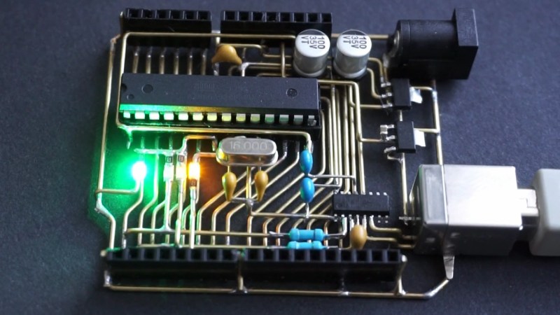
Microcontroller demo boards such as the Arduino UNO are ubiquitous on Hackaday as the brains of many a project which inevitably does something impressive or unusual. Sometime someone builds a particularly tiny demo board, or an impressively large one. In the case of the board featured here, the Arduino is a gorgeous labor of love which can’t really be called a board since there is no PCB. Instead of the traditional fiberglass, [Jiří Praus] formed brass bars into the circuitry and held it together with solder.
This kind of dedication to a project leaves an impression. His notes show he saw the barest way to operate an ATMega328, built it, tested, and moved on to the power supply to make it self-sustaining, then onto the communication circuit, and finally the lights. The video below shows a fully-functional Arduino happily running the blink program. He plans to encase the brass portion in resin to toughen it up and presumably keep every bump from causing a short circuit. The components are in the same position due to a custom jig which means a standard shield will fit right into place.
The Arduino started far less flashy yet nearly as fragile, and it has grown. And shrunk.


Damn impressive work ;)
Truly a thing of beauty. A multi-layer PCB …minus the PCB.
Very nicely executed, Jiří.
Daaaaannnggg…
That’s gotta be the coolest looking ‘duino I’ve seen.
Calling that “dead bug” is a bit of an insult, don’t you think? On Hackaday surely you are familiar with circuit sculpture…
+1 that was not what I was expecting when I read ‘dead bug’
Yes, when I hear the term dead bug, then the chip usually is upside down compared to most other components around them. Not to mention usually glued onto some kind of base, usually a copper plane on a board.
This circuit sculpture is far more tricky to pull off due to the very obvious lack of any kind of base to hold it all together during construction.
flip it all over and hold it to a base using Blue-Tak or double-sided tape or something, then carefully peel off once assembled.
For less damage, cast the pieces in ice and simply thaw.
It does look like the top surfaces of the major components are all co-planar, so this very well may have been the technique used. The double-sided tape method, I mean, not the cast-in-ice one.
Gawd, that’s gorgeous. “Hand-forged”, not “dead bug”.
“dead bug” is not pejorative here. It just means a circuit fabricated by placing the ICs with their leads facing up (in the manner of many deceased insects) and soldering wires directly to them, which is most likely how this was made.
Stunning handcrafted mastery
It’s as if it as “reverse etched” where the PCB substrate was dissolved, and left the traces intact. I can only imagine it would be hard to remove the shield once attached.
It would be REALLY impressive if the conductors here were flat copper strips, and cylindrical “vias” were used. Not that it isn’t really impressive anyway.
As for removing shields, nah, not that difficult. You just pry this off of the shield, one side at a time. Unless the shield is constructed similarly.
https://makezine.com/2009/12/07/arduino-skeleton-look-mom-no-pcb/
Really Good work…
That isn’t ‘dead bug’; that is ‘boardless circuitry’.
nice, very nice
Very nice! here a similar project from 2009:
https://make.kosakalab.com/obaka/arduino-skeleton/
If that thing had on a g-string and could dance around a pole I’d put in a dollar!
A Thing of Beauty!
Cyber-punk-duino!
All it needs, now, is a spring-loaded, wind-up power dynamo…
Looks like something intended for last year’s Hackaday Prize, but finished too late. Or was at least inspired by it. It certainly would have placed highly.
A nice piece of art.
I wonder how well SPI works with only a current limiting resistor on the D13 LED.