You could be forgiven for thinking that laser cutters and engravers are purely two dimensional affairs. After all, when compared to something like your average desktop 3D printer, most don’t have much in the way of a Z axis: the head moves around at a fixed height over the workpiece. It’s not as if they need a leadscrew to push the photons down to the surface.
But it’s actually a bit more complicated than that. As [Martin Raynsford] explains in a recent post on his blog, getting peak performance out of your laser cutter requires the same sort of careful adjustment of the Z axis that you’d expect with a 3D printer. Unfortunately, the development of automated methods for adjusting this critical variable on lasers hasn’t benefited from the same kind of attention that’s been given to the problem on their three dimensional counterparts.
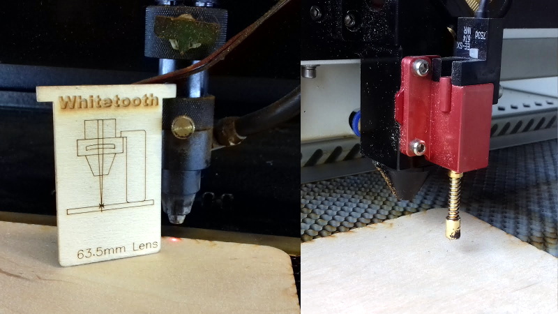
 Ultimately, it’s a matter of focus. The laser is at its most powerful when its energy is concentrated into the smallest dot possible. That means there’s a “sweet spot” in front of the lens where cutting and engraving will be the most efficient; anything closer or farther away than that won’t be as effective. As an example, [Martin] says that distance is exactly 50.3 mm on his machine.
The problem comes when you start cutting materials of different thicknesses. Just a few extra millimeters between the laser and your target material can have a big difference on how well it cuts or engraves. So the trick is maintaining that perfect distance every time you fire up the laser. But how?
One way to automate this process is a touch probe, which works much the same as it does on a 3D printer. The probe is used to find where the top of the material is, and the ideal distance can be calculated from that point. But in his experience, [Martin] has found these systems leave something to be desired. Not only do they add unnecessary weight to the head of the laser, but the smoke residue that collects on the touch probe seems to invariably mar whatever surface you’re working on with its greasy taps.
In his experience, [Martin] says the best solution is actually the simplest. Just cut yourself a little height tool that’s precisely as long as your laser’s focal length. Before each job, stick the tool in between the laser head and the target to make sure you’re at the optimal height.
On entry level lasers, adjusting the Z height is likely to involve turning some screws by hand. But you can always add a motorized Z table to speed things up a bit. Of course, you’ll still need to make sure your X and Y alignment is correct. Luckily, [Martin] has some tips for that as well.


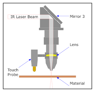
or you could just use a IR Distance Sensor
> Not only do they add unnecessary weight to the head of the laser, but the smoke residue that collects on the touch probe seems to invariably mar whatever surface you’re working on with its greasy taps.
I believe that smoke residue would also collect on IR sensor and render it inoperative after some time (which could perhaps cause lens head to crash into material).
What about just using a cap/cover to cover the probe after the probing sequence?
Trotec lasers have a super simple and effective tool for that. https://youtu.be/pE7jednm2Do?t=29
Our lasers have such a tool build right in. The problem starts when you have bigger sheets of natural material that are either not completely flat or have a bend to them. Making multiple probes and calculating the mesh like 3d printers do would actually be super helpful
Epilog has been doing this for years with their cutters. https://www.youtube.com/watch?v=6qUvCdEZ5VE
I did a project once where I had a 2.5D vacuum thermoformed piece of styrene, which easily fit in the range of the Z axis for my Lazer cutter. I needed to cut out a shape from the sheet to get my final object, but eventually had to cut it out on a bandsaw. I tried hard to configure multiple depths for the different layers (which usually control the power and speed settings). Would have been great if that Z axis was controllable from the user’s CAM for more than jogging.
If he’s etching metal, he could borrow a cue from seriously high end lasers and use a capacitive height sensor. The business end of the sensor is generally built into a nozzle for assist gas. Obviously, this won’t work on non-conductive materials, though.
Maybe use a kinect and 3D map the area.
Or perhaps get a web cam. Adjust the focus so it’s really macro. Add a couple of layers of cut up floppy disk as bad an ir filter and then get the size of the dot.
Reminds me of something I saw in the movie “The Dambusters”, the way the determined the height of the bombers was to use two angled spotlights shining on the water, when the two beams converged they were at the right height. Why not mount a another laser at an angle to the cutting laser, and when the cutting laser is at the right height the “target” laser converges with it and disappears, have it tracked with a camera, so it can automatically control the laser height, and so you won’t burn your eyes out.
https://en.wikipedia.org/wiki/Operation_Chastise#/media/File:Dambstrajj.gif
At the last (!) Makerfaire in San Mateo, I saw the Light Object booth where they had a live-Z tracking head. I’ve been on the hunt for such a critter, as material on a 4×3′ bed rarely lays flat all the way across the zone. $1850 for their alpha production run. It’s a stand-alone unit, not needing to be integrated with the controller:
https://www.lightobject.com/Real-time-tracking-Auto-Focus-Laser-Head-RTAF-P1143.aspx
Alternately, my earlier search in 2015 also found Ruida’s (rd-acs.com)unit that is a controller/PSU/driver all-in one solution. I seem to recall it being ~$4k all in. Here it is:
http://en.rd-acs.com/search.aspx?key=lfs-anm
RDC6332M – Laser controller – $650
LFS-ANM live focus system – $2000
Laser head for LFS-ANM (custom machine mount?) – $1450
Video of it in action:
https://www.facebook.com/watch/?v=1014115131934522
Haven’t pulled the trigger on either solution yet, as it’s still in my own wheelhouse to build one. I just have to get to the rationalization that I won’t have the _time_ to build one…
nothing new, really. We’ve had such an offset tool next to our lasercutter for, at the very least, 4-5 years now. We used to have auto-levelling on our cutter, but a couple of times it’s failed and resulted in the head going into the honeycomb with quite a bit of force, so, after one or two such incidents, we’ve removed the autofocus tool and now we stick to the “use the offset tool to level the cutter before using a material with different thickness” steps. Without levelling, the cutting can be truly atrocious, indeed – the difference between 3mm and 6mm seems to be large enough to impact the process severely.
I achieved the same ting with a head moving stepper from a CD and a 3d printed nozzle that held the lens.
The length of the nozzle was about 48.5 mm, focal length 50. A PIC wound the stepper down all the way and kept winding when it stalled against the work then rewound 1.5 mm.
Always in focus no matter what you put under it.
Do you mean you detected the stall, or you just drove it into the work piece and just let the motor skip steps? The latter is brute force, but kinda clever, assuming your workpiece wasn’t too soft for the lightweight stepper.