Screwy Math For Super Fine Adjustments: Differential Screws

For any sort of precision machine, precision adjustability is required. For the hacker this usually involves an adjustment screw, where the accuracy is determined by the thread pitch. This was not good enough for [Mark Rehorst] who wanted adjustment down to 10 μm for his 3D printer’s optical end-stop, so he made himself a differential adjustment screw.
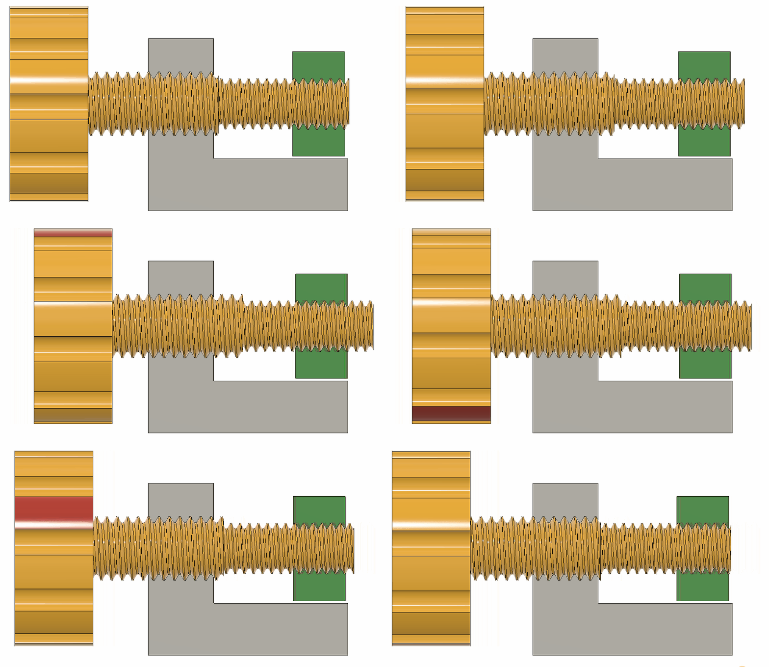
Tiny adjustment can be made to the green block due to the thread pitch differences

Differential screws work by having two threads with a slightly different pitch on the same shaft. A nut on each section of thread is prevented from rotating in relation to the other, and when the screw is turned their relative position will change only as much as the difference between the two thread pitches.

The differential screw in this case started life as a normal M5 bolt with a 0.8 mm thread pitch. [Mark] machined and threaded section of the bolt down to a M4 x 0.7 mm thread. This means he can get 0.1 mm (100 μm) of adjustment per full rotation. By turning the bolt 1/10 rotation, the  relative movement comes down to 10 μm.

This mechanism is not new, originating from at least 1817. If you need fine adjustments on a budget, it’s a very elegant way to achieve it and you don’t even need a lathe to make your own. You can partially drill and tap a coupling nut, or make a 3D printed adapter to connect two bolts.

Fabricating precision tools on a budget is challenging but not impossible. We’ve seen some interesting graphite air bearings, as well as a 3D printed microscope with a precision adjustable stage.

The Practical Approach To Keeping Your Laser In Focus

You could be forgiven for thinking that laser cutters and engravers are purely two dimensional affairs. After all, when compared to something like your average desktop 3D printer, most don’t have much in the way of a Z axis: the head moves around at a fixed height over the workpiece. It’s not as if they need a leadscrew to push the photons down to the surface.

But it’s actually a bit more complicated than that. As [Martin Raynsford] explains in a recent post on his blog, getting peak performance out of your laser cutter requires the same sort of careful adjustment of the Z axis that you’d expect with a 3D printer. Unfortunately, the development of automated methods for adjusting this critical variable on lasers hasn’t benefited from the same kind of attention that’s been given to the problem on their three dimensional counterparts.

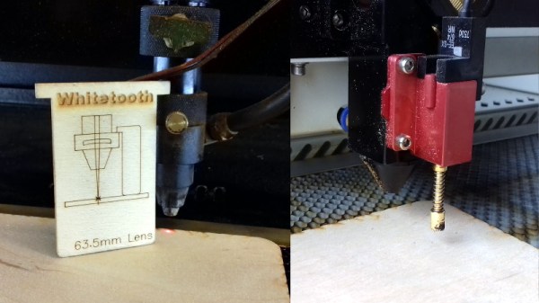
Ultimately, it’s a matter of focus. The laser is at its most powerful when its energy is concentrated into the smallest dot possible. That means there’s a “sweet spot” in front of the lens where cutting and engraving will be the most efficient; anything closer or farther away than that won’t be as effective. As an example, [Martin] says that distance is exactly 50.3 mm on his machine.

The problem comes when you start cutting materials of different thicknesses. Just a few extra millimeters between the laser and your target material can have a big difference on how well it cuts or engraves. So the trick is maintaining that perfect distance every time you fire up the laser. But how?

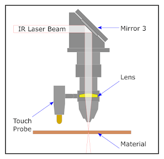
One way to automate this process is a touch probe, which works much the same as it does on a 3D printer. The probe is used to find where the top of the material is, and the ideal distance can be calculated from that point. But in his experience, [Martin] has found these systems leave something to be desired. Not only do they add unnecessary weight to the head of the laser, but the smoke residue that collects on the touch probe seems to invariably mar whatever surface you’re working on with its greasy taps.

In his experience, [Martin] says the best solution is actually the simplest. Just cut yourself a little height tool that’s precisely as long as your laser’s focal length. Before each job, stick the tool in between the laser head and the target to make sure you’re at the optimal height.

On entry level lasers, adjusting the Z height is likely to involve turning some screws by hand. But you can always add a motorized Z table to speed things up a bit. Of course, you’ll still need to make sure your X and Y alignment is correct. Luckily, [Martin] has some tips for that as well.

My precision mechanism adjuster. NSFW. As in if you use one of these to adjust a precision mechanism at work you'll get fired. Home use is fine tho;)

Fail Of The Week: My 3D Printer Upgrade

After years of cutting my hands on the exposed threads of my Prusa Mendel i2, it was time for a long overdue upgrade. I didn’t want to just buy a new printer because it’s no fun. So, I decided to buy a new frame for my printer. I settled on the P3Steel, a laser cut steel version of the Prusa i3. It doesn’t suffer from the potential squaring problems of the vanilla i3 and the steel makes it less wobbly than the acrylic or wood framed printers of similar designs.

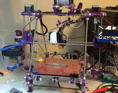
My trusty i2. Very sharp. It... uh.. grew organically.
My trusty i2. Very sharp. It… uh.. grew organically.

I expected a huge increase in reliability and print quality from my new frame. I wanted less time fiddling with it and more time printing. My biggest hope was that switching to the M5 threaded screw instead of the M8 the i2 used would boost my z-layer accuracy. I got my old printer working just long enough to print out the parts for my new one, and gleefully assembled my new printer.

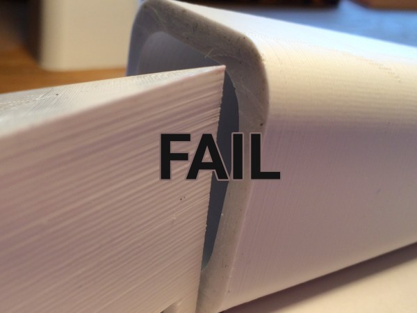
I didn’t wait until all the electronics were nicely mounted. No. It was time. I fired it up. I was expecting the squarest, quietest, and most accurate print with breathtakingly aligned z-layers. I did not get any of that. There was a definite and visible ripple all along my print. My first inclination was that I was over-extruding. Certainly my shiny new mechanics could not be at fault. Plus, I built this printer, and I am a good printer builder who knows what he’s doing. Over-extruding looks very much like a problem with the Z-axis. So, I tuned my extrusion until it was perfect.

Continue reading “Fail Of The Week: My 3D Printer Upgrade”