Plasma Cutting And 3D Printing Team Up To Make Bending Thick Sheet Steel Easier

Metalworking has always been very much a “mixed method” art. Forging, welding, milling, grinding; anything to remove metal or push it around from one place to another is fair game when you’ve got to make something fast. Adding in fancy new tools like CNC plasma cutting and computer-aided drafting doesn’t change that much, although new methods often do call for a little improvisation.

Getting several methodologies to work and play well together is what [tonygoacher] learned all about while trying to fabricate some brackets for an electric trike for next year’s EMF Camp. The parts would have been perfect for fabrication in a press brake except for the 4 mm thickness of the plate steel, which was a little much for his smallish brake. To make the bending a little easier, [tony] made a partial-thickness groove across the plasma-cut blank, by using a reduced power setting on the cutter. This worked perfectly to guide the brake’s tooling, but [tony] ran into trouble with more complicated bends that would require grooves on both sides of the steel plate.

His solution was to 3D print a couple of sacrificial guide blocks to fit the bed of the press brake. Each guide had a ridge to match up with a guide groove, this allowed him to cut his partial grooves for both bends on the same side of the plate but still align it in the press brake. Yes, the blocks were destroyed in the process, but they only took a few minutes to print, so no big deal. And it’s true that the steel tore a little bit when the groove ended up on the outside radius of the bend, but that’s nothing a bead of weld can’t fix. Good enough for EMF is good enough, after all.

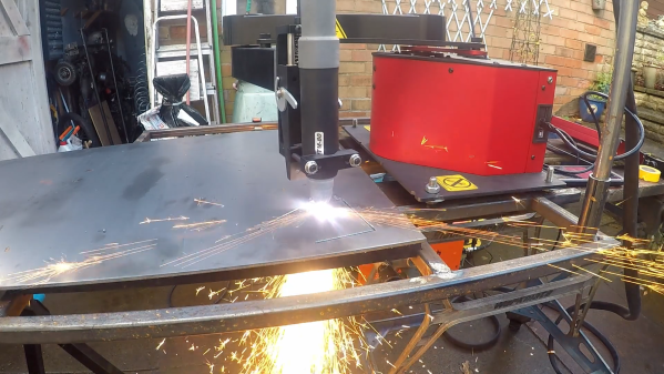
The brief video below shows the whole process, including [tony]’s interesting SCARA-like CNC plasma cutter, which we’re a little in love with now. This isn’t the first time we’ve seen 3D prints used as tools in metalworking, of course, but we picked up some great tips from this one. Continue reading “Plasma Cutting And 3D Printing Team Up To Make Bending Thick Sheet Steel Easier”

PCB sitting inside a 3D printed holder job, with holes to apply vacuum

Solder Paste Stencilling That Doesn’t Suck

Working with solder paste stencils can be a real faff, they rarely sit flat and move around when you so much as breath on them. [Unexpected Maker] airs his frustrations, and comes up with a simple solution, he simply makes a 3D-printed jig to align the PCB panel and applies his shop vacuum cleaner and hey presto!

If you’re ever been tempted to switch from frameless to framed solder stencils, then you’ll notice they can be rather awkward to work with. The usual online vendors have plenty of listings for stencil frame holders, but they do all seem to us, exactly the same, and more suited to stencilling T-shirts, than working with tiny PCB footprints.

The problem with unframed stencils is one of clamping and registration to the PCB, which framed stencils fix, when used with a jig that can dial in the rotation and translation errors.

But problem with those is, unless you have a perfectly flat support region all round the PCB, the weight of the frame tends to make the stencil bow up over the PCB, causing parts of it to lift away from the solder lands. This results in paste not being pushed into the places you want it, and instead it sticks to the stencil apertures and comes away when you lift it up. Most irritating.

You can try offset it by taping spare PCBs of the same thickness all around, but this is not always terribly successful in this scribe’s extensive experience doing this job by hand. [Unexpected Maker] solves this bowing issue by making a 3D printed jig that bolts to the stencil holder, takes a custom top plate with holes in, which in turns allows a vacuum to be applied from below. This sucks the PCB down to the jig, keeping it flat (in case it is also warped) and also pulls the stencil plate directly down to the PCB, making it also lie perfectly flat.

Continue reading “Solder Paste Stencilling That Doesn’t Suck”

The Practical Approach To Keeping Your Laser In Focus

You could be forgiven for thinking that laser cutters and engravers are purely two dimensional affairs. After all, when compared to something like your average desktop 3D printer, most don’t have much in the way of a Z axis: the head moves around at a fixed height over the workpiece. It’s not as if they need a leadscrew to push the photons down to the surface.

But it’s actually a bit more complicated than that. As [Martin Raynsford] explains in a recent post on his blog, getting peak performance out of your laser cutter requires the same sort of careful adjustment of the Z axis that you’d expect with a 3D printer. Unfortunately, the development of automated methods for adjusting this critical variable on lasers hasn’t benefited from the same kind of attention that’s been given to the problem on their three dimensional counterparts.

Ultimately, it’s a matter of focus. The laser is at its most powerful when its energy is concentrated into the smallest dot possible. That means there’s a “sweet spot” in front of the lens where cutting and engraving will be the most efficient; anything closer or farther away than that won’t be as effective. As an example, [Martin] says that distance is exactly 50.3 mm on his machine.

The problem comes when you start cutting materials of different thicknesses. Just a few extra millimeters between the laser and your target material can have a big difference on how well it cuts or engraves. So the trick is maintaining that perfect distance every time you fire up the laser. But how?

One way to automate this process is a touch probe, which works much the same as it does on a 3D printer. The probe is used to find where the top of the material is, and the ideal distance can be calculated from that point. But in his experience, [Martin] has found these systems leave something to be desired. Not only do they add unnecessary weight to the head of the laser, but the smoke residue that collects on the touch probe seems to invariably mar whatever surface you’re working on with its greasy taps.

In his experience, [Martin] says the best solution is actually the simplest. Just cut yourself a little height tool that’s precisely as long as your laser’s focal length. Before each job, stick the tool in between the laser head and the target to make sure you’re at the optimal height.

On entry level lasers, adjusting the Z height is likely to involve turning some screws by hand. But you can always add a motorized Z table to speed things up a bit. Of course, you’ll still need to make sure your X and Y alignment is correct. Luckily, [Martin] has some tips for that as well.

Hackaday guide to Lathes

Lathe Headstock Alignment: Cutting A Test Bar

Let’s say you’ve recently bought a lathe and set it up in your shop. Maybe you’ve even gone and leveled it like a boss. You’re ready to make chips, right? Well, not so fast. As real machinists will tell you, you can use all the levels and lasers and whatever that you want, but the proof is in the cut. Precision leveling gets your machine in the ballpark (machinists have very small ballparks) but the final step to getting a machine to truly perform well is to cut a test bar. This is a surefire way to eliminate any last traces of twist in the bed.

There are two types of test bars. One is for checking headstock-to-ways alignment, which is what we’re doing here. There’s another type used for checking tailstock alignment, but that’s a subject for another day.

Continue reading “Lathe Headstock Alignment: Cutting A Test Bar”

Clever Approach To Stylus Alignment

Digitally stored music is just data. But not long ago, music was analog and required machines with moving parts. If you have never owned a record player, you at least know what they look like, now that there’s a(nother) vinyl revival. What you may not be aware of is that the player’s stylus needs to be aligned. It makes sense, that hypersensitive needle can’t be expected to perform well if it’s tearing across a record like a drift racer.

There are professional tools for ensuring alignment, but it’s not something you’ll need each day. [Ali Naci Erdem] shows us his trick for combining a printable template with a mirror to get the same results without the professional tool costs. Instead of ordinary printer paper, he prints the template on a piece of clear plastic and lays it across a small mirror. These are both items which can be picked up at a hobby store, which is not something we can say about a record player mirror protractor.

We love music hacks like this informative introduction to circuit bending, the wonderful [Martin] from Wintergatan, or if you want to get weird, an organ made from Furbies.

Automating A Bowl Feeder With Arduino

Search for “bowl feeder” on Hackaday and you’ll get nothing but automated cat and dog feeders. That’s a shame, because as cool as keeping your pets fed is, vibratory bowl feeders are cooler. If you’ve seen even a few episodes of “How It’s Made” you’re likely to have seen these amazing yet simple devices, used to feed and align small parts for automated assembly. They’re mesmerizing to watch, and if you’ve ever wondered how parts like the tiny pins on a header strip are handled, it’s likely a bowl feeder.

[John] at NYC CNC is building a bowl-feeder with Arduino control, and the video below takes us on a tour of the build. Fair warning that the video is heavy on the CNC aspects of milling the collating outfeed ramp, which is to be expected from [John]’s channel. We find CNC fascinating, but if you’re not so inclined, skip ahead to the last three minutes where [John] discusses control. His outfeed ramp has a slot for an optical sensor to count parts. For safety, the Arduino controls the high-draw bowl feeder through an external relay and stops the parts when the required number have been dispensed.

We know, watching someone use a $20,000 CNC milling station might seem overkill for something that could have been 3D printed, but [John] runs a job shop after all and usually takes on big industrial jobs. Or small ones, like these neat color-infill machine badges.

Continue reading “Automating A Bowl Feeder With Arduino”

Sharing Virtual And Holographic Realities Via Vive And Hololens

An experimental project to mix reality and virtual reality by [Drew Gottlieb] uses the Microsoft Hololens and the HTC Vive to show two users successfully sharing a single workspace as well as controllers. While the VR user draws cubes in midair with a simple app, the Hololens user can see the same cubes being created and mapped to a real-world location, and the two headsets can even interact in the same shared space. You really need to check ou the video, below, to fully grasp how crazy-cool this is.

Two or more VR or AR users sharing the same virtual environment isn’t new, but anchoring that virtual environment into the real world in a way that two very different headsets share is interesting to see. [Drew] says that the real challenge wasn’t just getting the different hardware to talk to each other, it was how to give them both a shared understanding of a common space. [Drew] needed a way to make that work, and you can see the results in the video embedded below.

Continue reading “Sharing Virtual And Holographic Realities Via Vive And Hololens”