These days, brushless motors are the go-to for applications requiring high power in a compact package. It’s possible to buy motors in all manner of different configurations off the shelf, and the range available is only getting better. However, sometimes getting something truly optimal requires a bit of customization. With motors, this can involve swapping magnets or hand-winding coils. In these cases, it can be useful to test the modified motor to determine its performance. [JyeSmith]’s ESC tester is capable of just that.
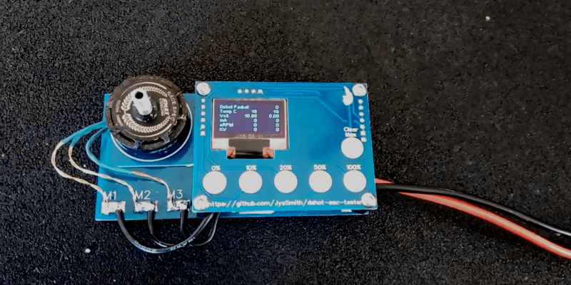
Fundamentally, the ESC tester is a simple piece of hardware. It uses a microcontroller to speak the Dshot protocol. This protocol is typically used to communicate between multi-rotor flight controllers and ESCs. In this case, the Dshot telemetry is instead displayed on a small OLED screen. This enables the user to read off KV values, as well as other useful data such as current draw and RPM. This can help quantify the effects of any modifications made to a motor, as well as prove useful for learning about parts of spurious origins.
It’s a device that should prove useful to those trying to eke out every last drop of performance from their multi-rotor builds. We expect to see more similar projects emerge as drone racing continues to increase in popularity. If you’re still trying to learn the theory behind the technology, you can always build your own brushless motor. Video after the break.
[Thanks to Keegan for the tip!]


In a previous job I designed dynamometers for small motors. The fundamental principle is pretty simple:
The motor under test it connected to the front of the dyno. (If I was doing this now I would use an ER16 collet to couple the motor shaft to the dyno)
Inside the box there is a second motor. This has the shaft connected to the input flange, and then the motor body is free to rotate around a set of bearings coaxial with the output. The motor body is then prevented from rotating by a load cell so that torque can be measured.
Under test the dyno motor would typically be run under closed-loop speed control, and then the characteristics of the test motor can be measured at a range of speeds and current / voltage / phase angle settings.
The smallest dyno we made was for motors < 10W, and that needed some rather elaborate frictionless suspension devices and bare-copper braided cable for the power / encoder / hall sensors. (the plastic insulation on conventional cable introduced unacceptable hysteresis)
This is awesome! Having a piece of test hardware like this is huge for playing with these motors.
Certainly great for comparative testing, for more absolute accurate results be mindful of any timing advance applied as this will affect kV. Load up on bus capacitance to help minimize effects of ripple voltage.
Phase resistance is also a super handy measurement. The hardware becomes more involved, maybe some custom firmware for the esc is in order? 😉
Looks great, slick packaging! Super interested to see some of your motors now!
This is really interesting.
I’ll have a read of the literature later. I’ve been looking for a hobby level brushless AC motor driver which can use hall effect sensors and have a sensible communication protocol for driving some wheels. I bought a malfunctioning (2010) Big Trak last weekend, and I want to make it much cooler.
I have been looking for something like that aswell, one that can handle some Amps and has the possibility for PID control of the motor’s RPM. I am currently using a YPG 100A ESC that can handle some RPM pid as it has a helicopter function. I am looking into more power though.. This gets way to hot quickly.
Hmm, useful for larger unit as dynamic braking?
Perhaps?
I just use a servo tester. But that is awesome for people developing motors.