Antenna tuning at HF frequencies is something that radio amateurs learn as part of their licence exam, and then hone over their time operating. A few basic instruments and an LC network antenna tuner in a box are all that is required, and everything from a bit of wet string to ten thousand dollars worth of commercial antenna can be loaded up and used to work the world. When a move is made into the gigahertz range though it becomes a little more difficult. The same principles apply, but the variables of antenna design are much harder to get right and a par of wire snippers and an antenna tuner is no longer enough. With a plethora of GHz-range electronic devices surrounding us there has been more than one engineer sucked into a well of doom by imagining that their antenna design would be an easy task.
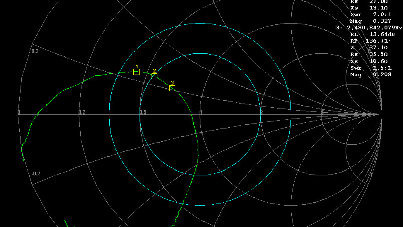
An article from Baseapp then makes for very interesting reading. Titled “Antenna tuning for beginners“, it approaches the subject from the perspective of miniature GHz antennas for IoT devices and the like. We’re taken through the basics and have a look at different types of antennas and connectors, before being introduced to a Vector Network Analyser, or VNA. Here is where some of the Black Art of high frequency RF design is laid bare, with everything explained through a series of use cases.
Though many of you will at some time or other work with these frequencies it’s very likely that few of you will do this kind of design exercise. It’s hard work, and there are so many ready-made RF modules upon which an engineer has already done the difficult part for you. But it does no harm to know something about it, so it’s very much worth taking a look at this piece.
It’s an area we’ve ventured into before, at a Superconference a few years ago [Michael Ossmann] gave us a fundamental introduction to RF design.


That looks like a great article. I’ve skimmed it but will read it in more detail when I have the time.
I’ve managed to successfully tune a 15.56MHz NFC antenna without a VNA although if I’d seen that article I might have gone for a miniVNA instead.
https://0xfred.wordpress.com/2018/12/07/nfc-antenna-tuning-without-a-vna/
Still no edit here on HaD? Obviously I meant 13.56MHz.
IKR…. it’s 2019 already.
Here’s my approach to “no-VNA” impedance matching for 2.45GHz ISM system: https://mightydevices.com/index.php/2019/08/complex-impedance-matching-using-scalar-measurements-math-and-resistors/
At 13.56MHz, your capacitors into the tens of uF sound really high. Are you sure it is the right values?
Once you past the self resonant frequency of a cap, the parasitics make them more like inductors.
The schematic shows the correct values measured in pf
I’m currently working on antenna design and not to confident yet. Playing around with VNA is a great deal of fun.
A few things to add to the article:
If you have a module and put it on your design the antenna design is only valid with all manufacturers recommendations in place. They will spec: track placement, amount of copper in the board, board thickness and many more. Many antenna design assume free air too. Having it inside an enclosure will likely de-tune the antenna. If you are going to match the antenna: Match it as realistically as possible. When mounted in the enclosure and if possible simulate the environment too.
For me that’s inside potting compound in fluid. Just to give a hint you can calculate the relative permeability and use it in your antenna design. Shortening the antenna by a factor of Sqrt(relative permeability) works I’ve been told..
It gets fun when you have a dielectric half space, like a circuit board or an antenna close to the earth. Even more fun, use water which shortens your antenna by 9 times! (Don’t complain about the losses, though.)
Really good guide. an important point worth repeating is calibrating as close as possible to the point where the tuning circuit is ok installed as possible. At GHz frequencies this needs careful attention. take not of the calibration reference plane. You may need to add an simulated electrical delay if you can’t calibrate at the precise point.
Another tip. Add one component at at time(closest to the first) calculate next components as you go.
At lower frequencies the distance of the transmission line had less impact so you don’t need to so careful.