[Mastro Gippo] recently purchased a wall mounted charger for his electric car that looked great and had all the bells and whistles he wanted. There was only one problem: the thing burned up on him. Looking to find out how this seemingly high-end piece of hardware gave up the ghost so easily, he took it apart and tried to figure out where things went wrong. While he’s not looking to sling any mud and actually name the company who produced the charger, he certainly has some choice words for whoever green-lit this particular design.
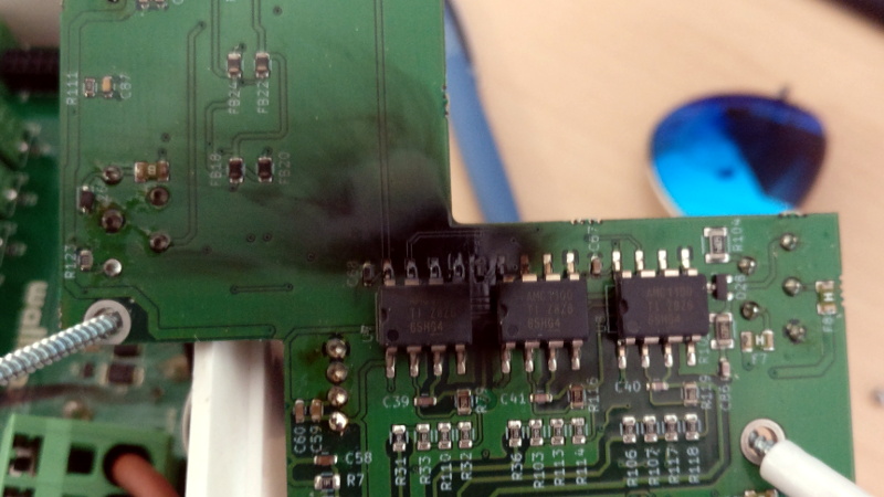
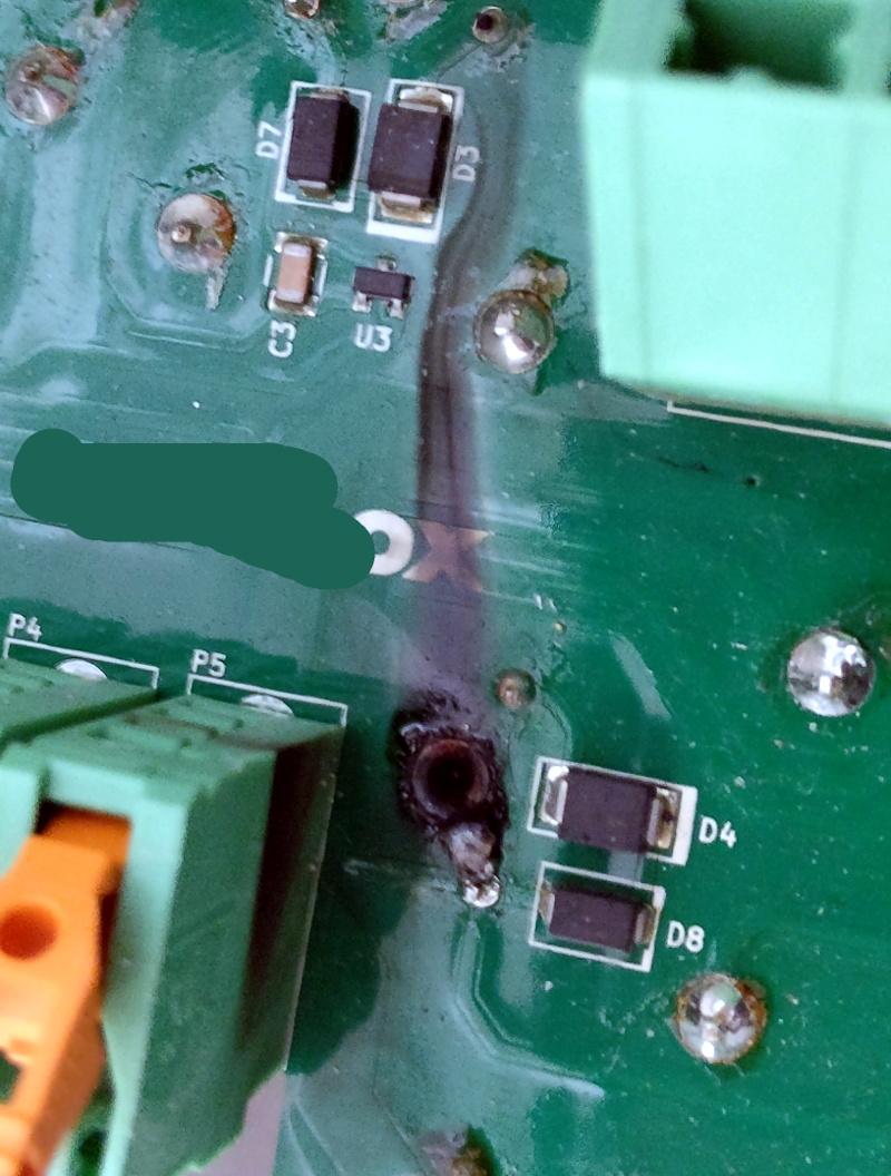 With the charger open, there’s little doubt that something became very toasty inside. A large swath of the PCB has a black char mark on it, and in some places it looks like the board burned right through. After a close examination, [Mastro] is of the opinion that the board heated up to the point that the solder actually liquified on some connections. This conductive flow then shorted out components below it, and things went from bad to worse.
But where did all the heat come from? [Mastro] was stunned to see that a number of the components inside the charger were only rated for 30 amps, despite the label for the product clearly stating it’s good for up to 32A. With components pushed past their limits, something had to give. He wonders how such a device could have made it through the certification process; an excellent question we’d love to know the answer to.
The worst part is, it looks like the designers might have even known there was an overheating issue. [Mastro] notes that there are heatsinks bolted not to a component as you might assume, but directly to the PCB itself. We’ve seen what happens when designers take a cavalier attitude towards overheating components, and the fact that something like an electric vehicle charger was designed so poorly is quite concerning.


Relying on the manufacturer to get the certification usually leads to shortcuts.
…see B474-MAX8 ;)
Reminded me of this issue in Dixtal ECG monitors models 2030, where one of the surface mounted fuses on the mains side of the PSU board would, instead of blowing and becoming open as expected, instead develop a resistance and get hot, somehow not hot enough to de-solder itself from the board, but enough to burn a hole right through it instead!
Sometimes it would open before burning a hole, therefore making the board serviceable by installing a glass fuse in it’s place. No more issues after that.
[Mastro Gippo]’s post was on July 31 and the manufacturer pulled their product August 1 and is no longer selling it. At least they’re listening to their community and doing the right thing going forward. Still some real rookie mistakes though.
Have they issued a recall, though? The thing is a fire hazard. If this was sold in the US, I hope Mastro Gippo had notified the Consumer Product Safety Commission.
AFAIK they’re still selling it, but I’m confident they are using proper relays now (that afaik were not available at the time this product went into production). While my post is recent, the event happened years ago, just a few months after I purchased the charger.
I looked up for recalls when writing the article but couldn’t find any; I certainly was never notified.
I don’t know about safety commissions here; we’re in EU, and consumer associations are pretty ridicule here.
Check if there are UL marks on the device. They can get involved if there are safety issues. i.e. fire hazard.
No UL, only CE :/
I was referring to ” If this was sold in the US”.
Interested in knowing the manufacturer. That, and the charger topology.
Do a reverse image search on the slightly-censored “glamor shot” of the product, you’ll find it. The manufacturer’s name rhymes with “mall dox”.
This must have been Made in China and with faked U/L approvals I bet, because from what they show this would never pass. There may have been oter flameouts that attracted the U/L and forced it off market?
If you look closely at the original post, it’s “Made in EU” and has a CE mark. Self-certification, I guess? Probably not meant for US market.
He’s in Italy.
Wallbox Commander is the unit
Yup, It’s in the article despite having many [retacted]. Even still there are enough details to find it with “3 phase 32a wall charger touchscreen”
“The worst part is, it looks like the designers might have even known there was an overheating issue. [Mastro] notes that there are heatsinks bolted not to a component as you might assume, but directly to the PCB itself.” – Can somebody enlighten me on why bolting (=anchoring) heatsinks to the PCB shows the designers were aware of a heating problem? Or does that mean there were heatsinks on the PCB itself, cooling the PCB (which would be hilarious)?
Ok, read the referred article. Fins on the PCB itself, for the PCB itself. That’s remarkable.
I have seen this for some products (frequently surface-mount components with a large pad on the underside serving dual roles of a ground connection and heatsink connection for the IC), also search for “metal core PCB” – common for LED lighting. One of 8devices’ SoM products actually requires a cutout underneath the SoM so that a heatsink can contact it. ( https://www.8devices.com/products/jalapeno )
But such an approach for through-hole relays??? WTF?
Fins are not for the relays, they are for the PCB itself!!! It heats up at high currents due to the copper tracks resistance. Check this: https://www.digikey.com/en/resources/conversion-calculators/conversion-calculator-pcb-trace-width
in some cases all manufactures of PCB’s that have high voltage and power running through the board place heat sinks on the board…..they are connected to the board with nuts and bolts but have a copper circuit/plate leading to the “hot” component which allows for the heat to bleed off thru the copper plate or tie downs……very common practice
For an electronics product, that label contains way too few symbols. Which is a tell tale sign that no actual certification was done.
Most likely some china import product, combined with too eager sales people. Not uncommon sadly.
Oh, and the name on the PCB hasn’t been scrubbed properly. You can see “..ox” on the photo here on HaD. And a blurry “Wall…” on another. Making the name something like “Wall..ox”. Someone else can most likely fill in the rest.
Wallbox Commander, someone above solved it.
I just don’t understand why go out of the way to hide who made this piece? If something could have burned down my house, I’d post billboards up and down the highway!
> [Mastro] was stunned to see that a number of the components inside the charger were only rated for 30 amps, despite the label for the product clearly stating it’s good for up to 32A.
It’s a 3-phase device, right? I’m no electrician, but doesn’t the 32A rating on the enclosure mean the _total_ current consumed by the device? The 30A components in question look like they handle single phase each. And why didn’t he complain that there’s “400V” written on the sticker, yet the relays are rated for 240V? ;-)
Or maybe it’s customary to round the rating to the nearest available circuit breaker like 16A, 25A, 32A?
400V is for 3-phase devices (since a single phase is only 230V)
Power systems aren’t my thing, but I thought current is generally specified per-phase, and it matches what I believe is their product page on amazon, 7.4kW single-phase / 22kW three-phase (22kW = sqrt(3) * 400V * 32A). That means each leg of the device should be handling 32A at 230V, unless their claimed total power is false.
Yeah, current is per phase, so single phase 230V would be 1x 32A, and three phase 400V would be 3x 32A, the amp is per phase.
Right, I should have looked up the datasheet, before writing nonsense. It clears up any doubts. Thanks!
You see this sort of thing in many Harbor Fright tools too… Their battery packs that are nominally rated at 10A continuous, 40A peak contain components whose absolute maximum rating (i.e. not recommended operating conditions, but the threshold above which the manufacturer expects damage to be likely) is at or even below the advertised peak.
It’s depressingly common for low-end electronics to skimp on engineering margin (high end units may build in a factor of 2, middle of the road 1.5, and the crummy ones may be more like 1.1 or in the case of my HF battery pack more like 0.8) and I find it distressing how the low-end products are now starting to leak past the predictable low-end brands, retailers, and price points.
If you go to HF or Banggood or whatever you know what you’re getting in to and are presumably willing to live with reduced durability and derate the stated specs by a factor of two. However when you go to a reputable retailer and buy a reputable brand and then discover that their “consumer” model is just a rebranded version of the same crappy product you’d have gotten at AliExpress or whatever and marked up due to the rebadging that just sucks (and it seems to be getting more common these days).
Perfect storm. Consumers want…ahem, affordable products, and manufacturers want maximum profit. What could possibly go wrong?
Aren’t HF tools single use then replace?
I work on software for EV chargers, and choosing a too low current rating is downright scary with these things. Quite some cars will continuously push the limit on their current allowance(or even exceed it by half an amp or so) when charging between 30% and 80%.
It looks like Tesla did a good job choosing the contactor, it’s such a huge one with good reason. This contactor will sometimes cut under full load if the vehicle is a bit unruly(teslas hardly are, though), I would not even trust this Wallbox Commander, erm [redacted], with its small relays to charge a hybrid.
The Chint contactor is probably a good choice, we haven’t had issues with those to my knowledge.
EV chargers bogle my mind.
In most of the world, a 240 Volt 13 Amp AC plug and socket costs ~$2, and consists of just 2 conductors and earth for safety.
Yet a 16 Amp EV charger consists of contactors, a residual current device, connectors with latches and microswitches, a 12 volt power supply, a microcontroller, earth impedance measurement, and a bunch of extra signalling pins. And the total cost is closer to $500.
Does the 3 extra amps really warrant all that extra equipment, cost and complexity?
Here are the reasons: http://www.mastrogippo.it/2019/07/ev-charging-basics/
Also, you may go up to 80A, or 63A 3-phase, so I’d say that yes, imho the safety (and the advanced features) are definitely worth the extra cost.
Thank you for buying the Wallbomb 2019 . Make sure to fill out the warranty care !!!
It’s a smoke detector tester.
Chinese PCB preheater https://www.amazon.com/gp/product/B01MCT9FAY/ref=ppx_yo_dt_b_search_asin_title?ie=UTF8&psc=1, which is 110V/1600W, comes with the power cable rated for 10A.
Wrap the cable round the PCB you want heated…
Should of bought a https://www.openevse.com/; buy one of the kits or one that comes put together.
Yikes, guess you didn’t even click the link to the original post.
Hey A-Hat! Yes, I did take the time to read everything and the original post. I was only stating that openevse is a sound design, and it was produced so it wouldn’t burn up.
You said “Should of brought a OpenEVSE” when literally the second paragraph of Mastro’s post said that he already built one and was looking to improve on some of its issues.
Why try to lie about reading it now?
Overheating products is planned obsolescence. Why else would a manufacturer embed a toasty chip in plastic (Samsung)? I have an old APC UPS, cold to the touch and lasted 25 years. The new UPS was a toaster, it lasted 3 years.
Dunno why everyone talks about unsafe stuff from China. Have seen same level of craptastic out of the EU products, only they charge more for poor stuff.
Have worked with Engineers from Japan, Taiwan, Korea, China, Malaysia, Brazil, Mexico, UK, Poland, Italy, Germany, Netherlands, Russia, and even Canada (but they talk strangely). The least competent companies were in Poland, UK, and Italy; mostly because they could not be bothered to understand their own directives or their national versions of the scoped safety standards.
At a previous employer, always got stuck with reviewing stuff from Asia and EU to see is suitable for submittal per North American product safety standards (NOM/SCC/NRTL). Asian designs were typically salvageable and some were either total duds or safety nightmares, but they always responded well to my red-lined schematics and construction drawings. Cannot say the same for the EU stuff that was reviewed.
I exclusively use contactors for my Hydra (I am proud to say that I designed the world’s first two-headed circuit sharing EVSE). The high current paths are done strictly with 8 gauge wire. The HV board has high voltage on it, but very, very low current.