Direction finding has long been a pastime of the ham radio community. Fox hunts and other DF events have entertained many, as they swept their antennas hunting for a transmitter. As with rock and roll and flared pants, time changes all things, and [Corrosive] has been experimenting with a very modern way to go about direction finding with SDR.
The work is made possible through the use of Kerberos SDR, a device which is essentially four RTL-SDR radios operating in unison. By fitting these with the appropriate antennas and running the right calibrations, the hardware can be used as a powerful direction finding tool.
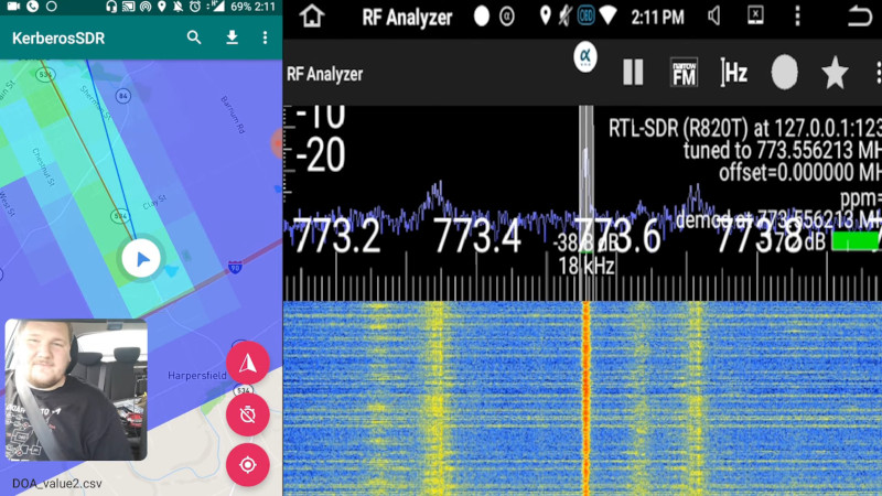
[Corrosive] demonstrates this ably, by fitting the rig to his car and driving around on the hunt for a transmitter. Hunting for a P25 control station, he demonstrates the configuration of the hardware to help find the FM modulated signal. The software part of the equation is integrated with GPS maps, so one can follow the bearing towards the signal source while data is collected. Over time, the software takes more samples until it builds up an expected location for the transmitter.
The setup is remarkably effective, and largely does all of the heavy lifting, leaving the user to simply handle driving the car. The heat mapping feature is also incredibly cool, and would look great in your next spy movie. We’ve featured Kerberos SDR before, and fully expect to see more great work on this platform. Video after the break.


I didn’t watch the video, but i imagine one first needs to “time-sync” the different modules on a known signal or something ? Anyone know how this is done ?
Its all on single board and they share a common clock signal.
The Kerbereos unit has four RTLs on a single board with a shared clock signal.
There is some stream synchronization still needed to be sample-accurate, and the Kerberos project had either a built-in noise source or a companion calibration board that would feed a noise signal to all four channels, permitting sample synchronization to be achieved.
I’ll point you to this: https://hackaday.com/2018/09/10/direction-finding-and-passive-radar-with-rtl-sdr/#comment-5026897
and say that I got 5 and 6 slightly wrong, but it is the same overall idea. instead of four RF switches, they are enabling/disabling the noise source and using four equal length inductive coupling tracks on a separate PCB to deliberately inject noise at the exact same time and phase into all four SDR’s (and antennas):
https://30.img.avito.st/1280×960/5626407930.jpg
I didn’t watch the video but I wanted to make a comment that would have been instantly answered had I watched the video. Can anyone help? Oh, and can you feed my cat while you’re at it?
Dude no need to so angry.
Can you point me at the number of minutes into the video where it was answered, because I must have missed it.
Some people absolutely hate videos as a means of transferring knowledge, preferring technical papers. Different people assimilate information optimally through different pathways – I personally did not see any problem with the bty’s question.