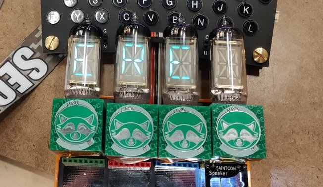
Tiny PCBAs and glowy VFD tubes are like catnip to a Hackaday writer, so when we saw [hamster]’s TubeCube tube segment driver we had to dig in to learn more. We won’t bury the lede here; let’s enjoy a video of glowing tubes before we go further:
The TubeCube is built to fit the MiniBadge badge addon standard, which is primarily used to host modules on the SAINTCON conference badge. A single TubeCube hosts a VFD tube, hardware to provide a 70 V supply, and a microcontroller for communication and control. Each TubeCube is designed to accept ASCII characters via UART to display on it’s display, but they can also be chained together for even more excitement. We’re not sure how [hamster] would be able to physically wear the beast in the video above, but if he can find a way, they all work together. If you’re interested in seeing the dead simple UART communication scheme take a look at this file.
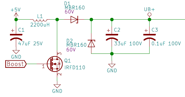
We think it’s also worth pointing about the high voltage supply. To the software or mechanically minded among us it’s easy to get trapped thinking about switching power supplies as a magical construct which can only be built using all-in-one control ICs. But [hamster]’s supply is a great reminder that a switching supply, even a high voltage one, isn’t as complex as all that. His design (which he says was cribbed from Adafruit’s lovely Ice Tube Clock) is essentially composed of the standard primitives. A big low voltage capacitor C1 to source the burst of energy which will be boosted, the necessary inductor/high voltage cap C2 which ends up at the target voltage, and a smoothing cap C3 to make the output a little nicer. It’s controlled by the microcontroller toggling Q1 to control the current flow through L1. The side effect is that by controlling the PWM frequency [hamster] can vary the brightness of the tubes.
Right now it looks like the repository has a schematic and sources, which should be enough to build a small tube driver of your own. If you can’t get enough TubeCubes, there’s one more video (of a single module) after the break.


You are burying the lede. The Saintcon badge is a pretty interesting looking Enigma Machine
I agree! Is there a write-up anywhere?
https://mobile.twitter.com/search?q=Saintcon
It’s got an FPGA for the LED array and a microcontroller for the Enigma Logic. They can be daisychained in circle.
I’ve been enjoying the super-gate photos! Was hoping there was a single writeup or talk I could point to though
There will be a writeup soon!
Great! Holler when there is!
Here is a Saintcon inspired writeup on how to use Sketchup to design complex PCB shapes for Fritzing…
https://arduinoenigma.blogspot.com/2019/10/get-your-head-out-of-clouds-and-design.html
Here’s the official badge writeup https://mkfactor.com/?p=100
Thanks!
I put an article up in the blog.
Cool!
what is a reason for the d2 diode? some kind of reverse polarity protection? but why?
It’s a Zener that’s reverse biased. If the booster goes over 60V it will start to conduct – which will limit the output of the circuit to 60V – ish to prevent damage to the tubes due to overvoltage.
In practice, the booster can pump more energy than the diode can clamp, so if you drive it too hard it tends to release its magic smoke. There’s no feedback to the drive circuit anywhere to regulate the output, since I don’t really care about the particular output voltage, more or less.
D2 is a reverse biased 60V Zener. It will start conducting if the output voltage of the circuit goes over 60-ish volts, to protect the tube from over voltage.
In practice, it’s possible to push too much power and cause the diode to emit the magic smoke. Ooops.
I’m not reading the output voltage and dialing in a boost level, it’s just freewheeling. For the most part I don’t care about the output voltage, and the tube has a wide range of voltage that it will operate at.
You know you can go in and change the value MBR160 into a different part#. It would complain no user changeable values, but it’ll let you change anyways. This would let you make a proper BOM. There are also Zener diodes in part libraries. :P
Personally, I would rather throw in a $0.10 MC34063 (or eqv) and let it regulate the voltage and not rely on a uC to act correctly – crashes, bugs etc.
I used a MBR160 in the prototype. The final had a surface mount variant with the same specs. I used a Zener symbol in the schematic, so I have no idea what your compliant here is.
As for the boost, the goal was minimal part count, and the ability to adjust the brightness on the fly. In this application I am not taking full advantage of this, it’s either on or off. However, it would be fun to be able to alter a digit brightness for visual sake. Beyond that, I was not sure going into this what would be a good voltage for the trade-off of power consumed vs brightness, so it made sense to be able to tune on the fly.
I understand there are lots of chips and designs out there to boost in a more controlled manner. Hell, I could have put a 555 in front of the mosfet to limit on time as well, but again: I wanted minimal part count.
You’re free to redesign and release your version.
MC 34063 has only one advantage: It’s cheap. And it’s lousy. But in this case, it is not capable of 60V. Why not use some feedback to an ADC input and a software control loop? Or is this there anyway.
Using a 60V Schottky as a Zener is a bad practice, badly defined breakdown voltage and perhaps destructive in the long run.