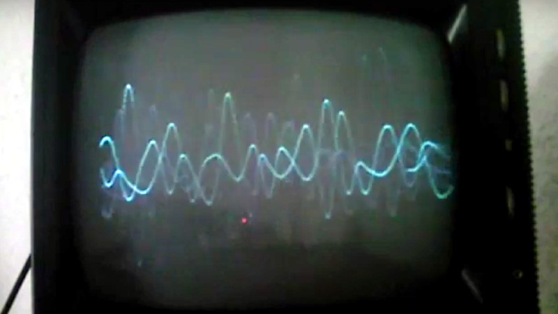
Guitar amplifiers are a frequent project, and despite being little more than a simple audio amplifier on paper, they conceal a surprising quantity of variables in search of a particular sound. We’ve seen a lot of them, but never one quite like [Nate Croson]’s CRT TV guitar amplifier. The LM386 doesn’t just drive the speaker, he’s also using it to turn the TV into a crude oscilloscope to form a visualisation of the sound.
The video showing this feat is below the break, and it puts us in a quandary due to being short on technical information. He’s driving the horizontal coils with the TV’s 50 Hz sawtooth field timebase, and the vertical ones with the audio from the LM386. We aren’t sure whether he’s rotated the yoke or whether the connections have been swapped, but the result is certainly impressive.
So given that there’s not quite as much technical detail as we’d like, why has this project captured our interest? Because it serves as a reminder that a CRT TV is a bit more than a useless anachronism, it’s a complex analogue device with significant and unique hacking potential. The older ones in particular provide endless possibilities for modification and circuit bending, and make for a fascinating analogue playground at a very agreeable price. It’s worth pointing out however that some of the voltages involved can make them a hazardous prospect for the unwary hacker. If you’re interested though, take a look at our dive into an older model.


I made several of these as a teenager by rotating the yoke. In hind site, assuming the windings were the same, it would’ve been simpler to just swap the vertical and horizontal connections but i never did it that way.
The best TV sets had a vertical hold control on the front. That allowed you to adjust the sweep frequency somewhat to get a stationary standing wave. The note B is at 61hz so you could use it for tuning too.
The windings are definitely not the same. At least in every set I came by. My favorite trick as a teenager was to take a small portable junk-tv, remove the clamp of the yoke and put a ‘pendulum’-weight on the yoke assembly. If you rotate the tv, the picture stays level. Amazing…
Anyway, in cheap solid-state TVs the horizontal section is, at least in my experience, very solid and keeps working even with the yoke disconnected. It’s not advisable to try that on a tube type set, though.
I never saw plans in a magazine for turning a tv set into an oscilloscope, but I did see classified ads for plans in the back of magazines. Maybe the magazine had articles early on, but I’ve seen manh a back issue.
Q&A columns were common and I remember there once was a question about doing this, and the reply was “don’t waste your money”. The reply was generally valid, too little bandwidth, not much sweep range, so not useful for general purpose.
But yes, useful for some specific purposes, like showing an audio display. You can make patterns with quadrature oscillators and that would look good on a screen larger than tge average oscilloscope, but I can’t remember if I saw that done.
The one thing I do remember was about 1972. Someone buiot a display to show all of the five HF ham bands at once, and used a tv set for a large display.
Michael
1971 I did the big 19inch audio scope in high school, a year or so ago I did it to a cute little 5inch cube of a TV. I used it’s built in radio as the input to display. A local legend Surplus and Salvage closed suddenly or I would have gotten 3 more sized TV’s and a karaoke box with stereo sound and the boob tube. Sadly Goodwill will not take any CRT’s anymore. Get em while they are around!
The big trick to pull off is leaving a suitable load of a coil on when the horizontal deflection coil is disconnected from the flyback-SMPS HV source. From what I remember the impedance of the two coils favor the different frequencies that they operate on. So audio gets the wider bandwidth horizontal rotated to now vertical and the 50-60hZ vertical is unchanged as the timebase.
The technical details are pretty simple. You disconnect the both the horizontal and vertical coils. Connect the lower-frequency vertical wires to the horizontal coil instead, then connect an auxiliary audio out to the vertical coil. A regular 1/8″ jack for driving headphones is fine. As far as video input, just leaving it tuned to a dead channel will provide enough light to illuminate the line. Try not to get a later CRT that suppresses video static. Not totally ideal, but it’ll work for something cosmetic like this.
“It’s worth pointing out however that some of the voltages involved can make them a hazardous prospect for the unwary hacker”
https://lowendmac.com/2007/the-truth-about-crts-and-shock-danger/
tl;dr: the high-voltage section really isn’t nearly as dangerous as it’s hyped up to be. You should focus your care on the power supply part of the board where caps that smooth out rectified mains voltage live, and also the ones in the low-voltage supply. Those should have bleed resistors anyway, so in almost every case they are also harmless if you unplug it and leave it a minute before going to work. Discharge ’em with a screwdriver anyway. But most of this common and incorrect “CRT safety advice” will have you overlooking those in favor of tiptoeing around a part of the circuit that will give you a little jolt but has far too little total energy to kill you. I’ve been sparked by the anode nipple many, many times. It’s fine.
Most of the CRT panic is based on certain very old models that actually were pretty dangerous. But you really won’t find one of those sitting around in a thrift store anymore.
Well, y’kow, we have to make the disclaimer.
I cut my teeth on live chassis sets. Those were a bit of a hazard.
I’m still all for the disclaimer, just saying the part one ought to side-eye is not the one most people think.
He definitely has that cheap electric 6 string Blues sound going on.