[Jan] is solving a problem many of us have had, deeply discharging our project’s batteries and potentially damaging the cells.
His board can handle batteries from 6 to 34 volts and supports both LiPo or Lion batteries. The board can be flexible about its cut-off voltage. It also has a feature we really like; the user can set a delay before it shuts off the battery: useful in cases where a heavy peak current draw causes the battery to operate at a lower-than-threshold voltage for a few seconds. Once the board is shut down it takes a manual reset to allow power to be drawn again.
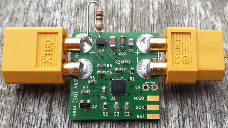
His latest iteration of the board is an impressive 1 sq. inch in size! This can fit in just about any project and it’s even flexible in the choice of battery connector. Next time we have a high current draw project with expensive batteries or maybe a monitoring device that’s expected to run a long time we may throw one of these boards in there just to be safe.


Wouldn’t a high inrush of current melt those solder joints the connectors are connected to?
Yes
depends on the duration and power. to me it seems the amount of brass can pipe away a lot of heat before things start to melt.
At 100 amps discharge current, which is easily possible with these LiPo packs, even 0.1 Ohms at the joint will generate a kilowatt of heat (I2R loss). This may be caused by a soldering fault, corrosion, or mechanical failure like cracking in the joint. Since this power is concentrated at the solder joint where the resistance is highest, the solder will melt quickly before the heats gets conducted to the brass, and the connector lifts off of the board.
What happens next depends on luck. When the connection is broken, it’s likely that the current will sustain an arc which increases the amount of heat being dumped into the board, and it catches fire.
Ive seen over 80 amps on my XT60 connectors for 15-20 seconds at a time… never had anything desolder or even gotten close to hot enough
That’s because the connector is designed for it.
It is not designed for being soldered flimsily on one corner to a PCB.
There are XT60 meant for board mount, Those ain’t them.
XT60PW-F XT60PW-M
Hi, I am the creator of the project and am surprised to see it here. It’s a work in progress :)
There are >6mm wide copper traces under the board which go from IN to the MOSFET to OUT. It is intended to handle up to 10A of current, which it easily does without getting warm.
@Dave Null: yes, I got 20 of them but haven’t included them yet in the design because it’s a test board and too small for it.
Trouble is, many 6s or 8s LiPo packs will happily give you 100+ Amps of current.
Yep, you’re totally right. I will add some info on the board to draw like 200W max.
It is not trivial to add protection which is fast and small enough for short circuit or over-current events. There are ratings you must obey to not destroy a given piece of tech. It’s the same here…
Or, you could add a simple 10 Amp 5×20 fuse.
Relying on “must obey” is a sure way to get an electrical fire, because at some point someone or some thing just won’t.
Like a small screwdriver dropped onto your electronics, or accidentally touching the power buses of your drone against the carbon fiber body…
Have a look at the automotive low side switches. They are pretty much smart MOSFETs which can turn off in case of too much current, too hot etc. Some even have a separate pin that you can use to monitor the consumption of the device. They are made by quite a few manufacturers.
Example: https://www.infineon.com/cms/en/product/power/smart-low-side-high-side-switches/automotive-smart-low-side-switch-hitfet/bts3011te/
@electrobob I looked into all that stuff when I began with that circuit.
Automotive low side switches do not handle the voltages I need to switch. there are are solutions for 48V systems but those are super expensive …
My first thought was that it was a fancy “smoke stopper” but after reading the first little bit of the article, I have to wonder what the discharge rating of the board is?
With XT60 connectors on it, theoretically it could be used in applications that would likely evaporate the traces, never mind potentially overheating and melting the solder on the edges.
As a possible revision suggestion, the battery connection PCB pads look almost like they may have been intended to allow the connectors be pushed into them from the bottom of the board, reducing the solder volume and resistance, but if not it could have been designed with notches out to the edge to fit the lugs into, rather than laying them on the top of the board.
Hi Josh, see my above comment. I just soldered XT60s to the board because all my LiPos use them. Nowhere does it say the board can handle 60A or more. It can safely switch 10A though. Could only test it to 180W yet because that’s what my electronic load is capable of turning into heat…
Again, it is a test revision.
As long as a heavier load never gets attached to it, that makes a lot of sense.
My concern is that I have access to (and use) XT60 connectors in a variety of applications, and some draw upward of 60A, at least in spikes, so I’m cautious about what I put in the circuit.
That said, knowing your design load and supply capacity is always a good thing!
I had poked around on your project page looking for a current spec before posting, but didn’t see anything but the current consumption specs.
This is a great idea for general application use of LiPo batteries, and I’ll definitely be interested in seeing how this plays out as your project continues.
Have an accidental short circuit down the line and the board evaporates, and then you run the risk of the solder blobs or other loose piece of metal touching and sustaining an arc between the battery leads, which will destroy your battery and cause a fire.
Just because your load is designed to only draw a certain amount of current, doesn’t mean it cannot exceed that current in a fault.
The 10 ohm resistor hanging off was to said to help the inrush current to the regulator because it kept blowing without it.
There are not even the required caps around the regulator for starters, and if you need a resistor to limit the little current that board would draw it’s time to ditch the regulator your using, or your design is seriously flawed.
Hi Mike, the Rev.6 boards have the proper caps directly next to the regulator and guess what: The regulator doesn’t even care if there’s a load connected. At some point it just decides to blow. This happened to brand name regulators as well. Even on breakout boards with no load or light loads connected.
I can’t tell you why exactly, but they sometimes just release magic smoke. The 10R botch resistor gets rid of that problem. Is it textbook design? No. Does it work? Yes.
Designing high power system and have that problem all the time with my ZXTR2012 12V regulators. I solved this by putting a schottky diode across vin/vout.
It seems that there is a 100ns spike on startup that causes them to blow.
Thanks for that tip! I tried this and other things with earlier revisions. They blew less often but still did it. I guess my scope wasn’t fast enough to capture the spike (which I think could be the same in my circuit). What I saw were voltage overshooting at the output, this is why there’s a 5V6 zener in the 5V rail.
Problem was the uC fried as well when the regulator released the smoke, that stopped with the zener.
Cheers, Jan
Some regulators don’t like it when there’s no load. They become unstable, which means they can run into oscillations which quickly overheat the regulator. Consult the data sheet for the recommended minimum load.
Secondly, if you drive a reactive load such as a motor or a speaker coil, the output side of the regulator can jump above the input, and LDO regulators really don’t like that. They get damaged rapidly, which is why it’s a common practice to put a diode from output to input, to limit the amount of reverse over-potential.
The reason:
“Usually a linear regulator will require a minimum load current to maintain regulation, the reason being a typical linear regulator cannot sink current, only source it. Since there are usually other control currents that flow to the output pin, then even with the pass element off if there is no load the output voltage can rise above it’s desired voltage because there is “nowhere for the current to go”.”
That’s why when the load is off, the regulator should be turned off by pulling the enable down. While the input may handle up to 40 Volts, the output side doesn’t necessarily do so, and when the voltage at the output shoots up due to a no-load condition, the chip goes pop.
Hi Luke, thank you a lot for your helpful input.
I will try the diode from output to input method! The regulator is a always on type which has 20mA short circuit protection with no enable: https://datasheet.lcsc.com/szlcsc/1810201512_Nanjing-Micro-One-Elec-ME6203A50M3G_C92717.pdf
As said earlier, this is totally a work in progress, the article was written without me knowing about it and the next revision will look more like the original idea (with three pots) and use an Attiny816 instead of the Attiny861.
I will look into short circuit protection too! Cheers, Jan
Love it!
Four comments and I’ve already learnt stuff.
That’s what we are here for right? I would’ve liked the article to show the final product which I still work on. But I did not even know there was an HaD article because I did not get messaged about this feature ;)
There’s so much going into the final design which I work on at the moment… Sometimes I’d love if people made the effort to at least skim though the logs I wrote. All the problems I encountered are laid out there. e.G.: https://hackaday.io/project/164742-universal-undervoltage-lockout-up-to-34v-input/log/164756-04-unpredictable-regulator-fails-help
Awesome project, keep up the good work.
Any decent BMS is going to have undervoltage lockout.
I think Jan addresses why you might want a programmable UVLO in the project details/logs. Well worth a read.
I got excited when I saw high current in article. Immediately started dreaming of 200A+ e bikes. Under 1-10a is what I’d call low current. Shame Gerrit Coetzee. Shame.
Feel free to add a mosfet driver, modify the board and parallel a few mosfets. You’ll easily get there, that’s how the ebike and RC manufacturers do it.