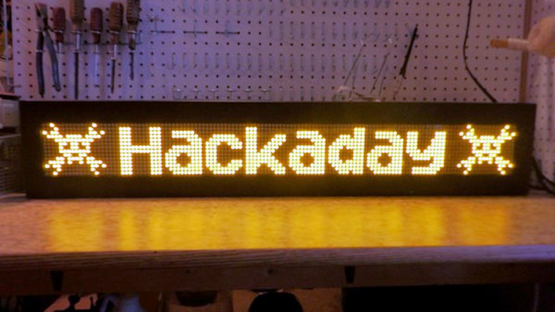
When his makerspace was gifted a pair of Luminator LED signs of the sort you might see on the front of a bus, [PWalsh] decided to pull one apart to see what made it tick. Along the way, he managed to reverse engineer its control protocol and replace its original control board with a WiFi-connected Raspberry Pi. Now they can use the LED signs to show whatever they want; no bus required.
As they were designed for automotive use, the signs were wired for 12 volts DC. So the first order of business was fitting it with an AC/DC converter so it could be plugged into the wall. After he measured the display’s current consumption, [PWalsh] estimated it’s maximum energy consumption and determined an old ATX computer power supply was more than up to the task.
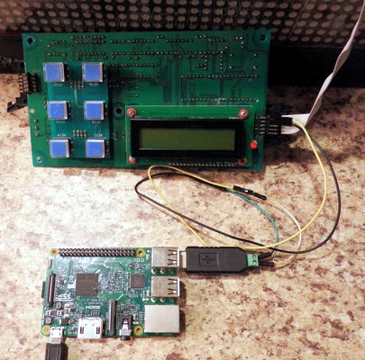 With the sign happily running battery-free, he could begin figuring out how to talk to it. Noticing a MAX485 RS-485 converter on the PCB, gave a pretty good idea of what language it was speaking, and with the aid of his trusty oscilloscope, he was able to suss out the baud rate. A cheap USB to RS-485 converter was then wired in between the sign and its control board so he could sniff the data passing over the line.
From there, the final piece of the puzzle was studying the captured data and figuring out the protocol. [PWalsh] was able to identify packet headers and ASCII characters, and pretty soon knew enough about how the sign communicated that he was able to remove the control board entirely and just push text and images to it right from the Pi. He’s even made his framework available for anyone else who might have a similar piece of bus-signage laying around.
Even if you’re not looking to add one of these signs to your lab, this project is a fantastic example of protocol reverse engineering with low-cost tools and simple techniques. We always love to see the process broken down step by step like this, and our hat’s off to [PWalsh] for delivering the goods in a big way.
This isn’t the first time we’ve seen these sort of LED signs get the “Internet of Things” treatment, and if you’re content with a somewhat scaled down version, you could always just build your own display rather than waiting on the local public transit vehicle to get parted out.


Finally they get put to good use! Those LED bus signs are terrible for busses. They don’t have enough space to show the route number, stop requested, and the next stop at the same time, so if you aren’t good with directions they don’t help much at all, you have to wait a long time for the info you want.
Ah come on, sometimes they are used appropriately … https://i.imgur.com/kmuNdSV.jpg
At first I got “Image cannot be displayed because it contains errors” message.
But when I right clicked “Reload Image”, it came up okay.
same here. maybe it was part of throttling hotlinked traffic specifically from this website. or project
Ah yes my bad, that is in fact an example of a bus using one correctly!
I think was just an industrial standard power supply, not an ATX (which requires more mods to make it work, example https://enricosanino.wordpress.com/2014/12/03/the-classic-hardware-hacking-atx-power-supply/)
According to my experience, (most?) ATX PSUs these days do not require a minimum load at 5V (like the old AT-PSU often did). So you only need to ground the PS_ON signal, I think it is the green wire on the connector.
I did a project like this for a 1990s-era LED sign that had a burnt out Z80. It had chained shift registers that you would feed a whole row into, with a row-select pin to latch all the shift registers into that row. My first project with an STM32. It still sits in the bar, it’s been working since 2010. But someone threw away its keypad that I’d bothered to be compatible with. Sigh.
I obtained an Allen-Bradley 2706 LED display that has an ethernet connector on it, and I found some old software to run on an old PC to talk to it, but haven’t done that yet. (Holiday messages for the neighbors?).
It did not come with the keyboard/setup module.
I think they are using an industrial PSU, not an ATX one. Using an ATX might require a bit more hacking around (i.e. https://enricosanino.wordpress.com/2014/12/03/the-classic-hardware-hacking-atx-power-supply/)
I know some of the programmers at Netscape did this back in the 90’s, and even pointed a webcam at it to allow people from all over the word to send messages to it. (Given that most of us were still on dial-up at that point, it didn’t work very well)
All I can find now though is this slashdot post from 1998 with a bunch of dead links:
https://tech.slashdot.org/story/98/05/11/090900/netscape-engineering-sign
Cool project.
Ahhh cool! I’ll look into his project to revive my flipdot bus project!
ICYMI, Hackaday has featured a number of flip dot projects over the years,
e.g.
https://hackaday.com/?s=flip+dot