RS-485 Sprinkler system

RS-485 Sprinkler Control: Scaling Irrigation Across The Farm

Building your own sprinkler system controller isn’t that difficult on the face of it, but what happens when your system starts to grow, adding more distant areas? To tackle this, [Vinnie] leveraged the tried-and-true RS-485 differential pairs to communicate reliably with ever-more-spread-out valves on his farm’s irrigation system.

The system uses a Raspberry Pi to control when each valve turns on and for how long. It does this via a custom RS-485 valve master board, whose code and design files are on GitHub. The master board communicates with the Pi over I2C and issues RS-485 commands while controlling the 12V line to the valves. Toggling the 12V supply is a smart move it lets [Vinnie] save power by not keeping the valves energized when idle.

At the valves themselves lives a valve node board (also on the GitHub repo). Each node has a unique address so it knows when its name is called to open or close a valve. The valves are latching solenoids, ideal because they don’t require constant current during the watering cycle. The Valve Nodes also support their own protocol to report state, firmware version, and allow in-situ configuration.

Be sure to head over to [Vinnie]’s project page and check out all the work that went into this great DIY irrigation control system, along with the thoughtful boards and tools he made to help others set it up. This is a welcome addition to the sprinkler-related projects we’ve seen.

Fail Of The Week: Subscription EV Charger Becomes Standalone, Briefly

At this point in the tech dystopia cycle, it’s no surprise that the initial purchase price of a piece of technology is likely not the last payment you’ll make. Almost everything these days needs an ongoing subscription to do whatever you paid for it to do in the first place. It’s ridiculous, especially when all you want to do is charge your electric motorcycle with electricity you already pay for; why in the world would you need a subscription for that?

That was [Maarten]’s question when he picked up a used EVBox wall mount charger, which refused to charge his bike without signing up for a subscription. True, the subscription gave access to all kinds of gee-whiz features, none of which were necessary for the job of topping off the bike’s battery. A teardown revealed a well-built device with separate modules for mains supply and battery charging, plus a communications module with a cellular modem, obviously the bit that’s phoning home and keeping the charger from working without the subscription.

Continue reading “Fail Of The Week: Subscription EV Charger Becomes Standalone, Briefly”

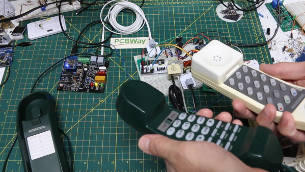
Two landline phones connected to a set of wires and boards

How To Build Your Own Analog Phone Network

Analog phones may be nearly obsolete today, but having served humanity for well over a century they’re quite likely to pop up in drawers or attics now and then. If you’ve got a few of them lying around and you think it’d be cool to hook them up and make your own local telephone system, check out [Gadget Reboot]’s latest work. His video series shows all the steps towards making a fully-functional wired phone system.

Of course, dedicated phone exchanges for home or small business use are not hard to find, but [Gadget Reboot] decided it would be way more interesting to design his own system from the ground up. To begin with, he used off-the-shelf subscriber line interface circuits (SLICs) to implement the correct voltages, currents and impedances to drive analog phones. He then added a DTMF decoder chip to allow the phone to dial a number, and hooked up both systems to an ESP8266 which controls the entire system. It implements the different states of picking up, dialing, ringing and hanging up, and also generates the corresponding audio signals.

The system becomes even more interesting through the implementation of a multi-exchange layout, just like in large-scale phone systems: when a number is dialled that’s connected to a different exchange, then a connection must be made between two exchanges in order to complete the call. Large-scale systems use dedicated protocols like SS7, but [Gadget Reboot] preferred to keep things simple and used an RS-485 connection. The two ESPs check each others status and if everything’s in order, a relay connects the two lines and the circuit is completed.

The current system is a bit of a mess of wires, but it works, and [Gadget Reboot] plans to make a cleaner setup based on custom circuit boards, possibly expanding it with functions like modem support. In any case it’s already way more advanced than a simple electromechanical system. Want to know more about classic phone networks? We’ve got you covered.

Continue reading “How To Build Your Own Analog Phone Network”

Hacker Dictionary: RS-485 Will Go The Distance

RS485 is a communication standard that should be part of the advanced hardware hacker’s arsenal; it’s not commonly encountered, but powerful exactly when you need it. It’s a physical layer interface for wired communications that uses a single differential pair for noise immunity, has good long-distance properties, and allows many connections to a single bus. Because of that, you will encounter it in security systems and even cameras, wired sensor networks, DMX512 lighting and all sorts of industrial electronics. For our hobbyist goals, you can absolutely use RS485 to build your home (or room) automation system, or a relatively large robot – without all those worries that wireless brings.

The name might remind you of RS232, and that’s because both RS232 and RS485 are standards that come from EIA (Electronics Industries Alliance). It also might remind you of RS422, if you’ve ever seen this name mentioned online – RS422 and RS485 are closely intertwined, sharing most of the physical layer, and I’ll show how exactly they relate. Continue reading “Hacker Dictionary: RS-485 Will Go The Distance”

USB Adaptor Isolates Multiple Serial Interfaces

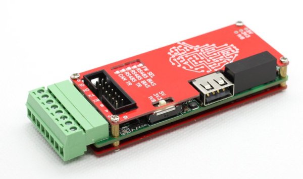
You need a Swiss Army knife of serial communications? Ollie is a compact isolated USB adaptor that provides USB, CAN bus, and two UARTs at logic, RS-232, and RS-485 signaling levels, as well as an isolated power supply.  [Slimelec] has managed to squeeze all this into a package the size of a harmonica.  We like the technique of making the enclosure from PCB material, complete with clearly labeled switch, LED and connector pinout names.

So far, only the compiled firmware is available for this project, but hardware files, and presumably the source code and documentation, are coming soon.

The central themes here are  isolation and flexibility. We can’t find the isolation voltage in the project specifications, but the CANable project on which this adaptor is based provides 2.5 kV galvanic isolation.  A single isolated USB interface is also provided over a standard Type A connector. The four-wire logic-level UART signals are available on a 2 x 7 box header, and are voltage selectable.  The RS-232, RS-485, and CAN signals are on an 8-pin pluggable screw terminal block, or you can use a DB9 connector with a pluggable adaptor board.

Whether you need a troubleshooting aid for field testing, are using CAN bus on your projects, or just want to isolate your expensive computer from sketchy prototype hardware, have a look at this project.

Heater Joins The Internet Of Things With ESP32 Board

The wood-burning heater [g3gg0] has at home works perfectly, except for one flaw: the pellet reservoir needs to be manually refilled every few days. Humans being notoriously unreliable creatures, this critical task is sometimes overlooked, which naturally leads to literally chilling results.

With automatic fill systems expensive and difficult to install, [g3gg0] wanted to find some kind of way for the heater to notify its caretakers about any potential fault conditions. Not just the fact that it was out of fuel (though that would naturally be the most common alert), but any other issue which would potentially keep the heater from doing it’s job. In short, the heater was going to get a one-way ticket to the Internet of Things.

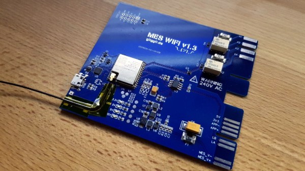
As it turns out, this task was not quite as difficult as you might expect. The Windhager heater already had upgrade bays where the user could insert additional modules and sensors, as well as a rudimentary data bus over RS-485. All [g3gg0] had to do was tap into this bus, decode what the packets contained, and use the information to generate alerts over the network. The ESP32 was more than up to the task, it just needed a custom PCB and 3D printed enclosure that would allow it to slot into the heater like an official expansion module.

When an interesting message flashes across the bus, the ESP32 captures it and relays the appropriate message to an MQTT broker. From there, the automation possibilities are nearly endless. In this case, the heater’s status information is being visualized with tools like Grafana, and important alerts are sent out to mobile devices with PushingBox. With a setup like this, the Windhager will never go hungry again.

Continue reading “Heater Joins The Internet Of Things With ESP32 Board”

Reverse Engineering An Old Bus Display

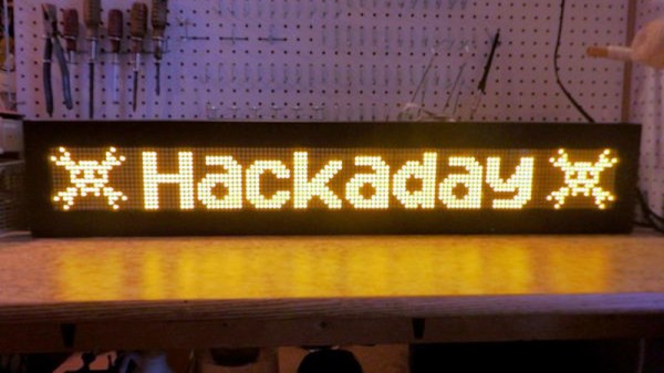
When his makerspace was gifted a pair of Luminator LED signs of the sort you might see on the front of a bus, [PWalsh] decided to pull one apart to see what made it tick. Along the way, he managed to reverse engineer its control protocol and replace its original control board with a WiFi-connected Raspberry Pi. Now they can use the LED signs to show whatever they want; no bus required.

As they were designed for automotive use, the signs were wired for 12 volts DC. So the first order of business was fitting it with an AC/DC converter so it could be plugged into the wall. After he measured the display’s current consumption, [PWalsh] estimated it’s maximum energy consumption and determined an old ATX computer power supply was more than up to the task.
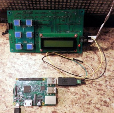
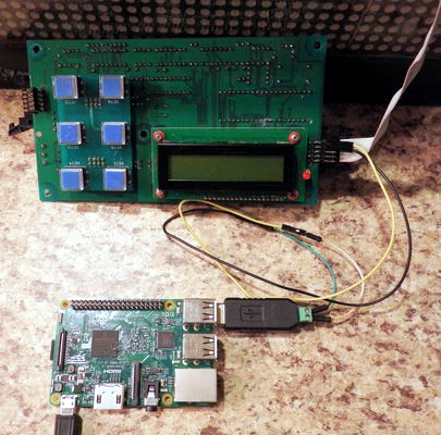
With the sign happily running battery-free, he could begin figuring out how to talk to it. Noticing a MAX485 RS-485 converter on the PCB, gave a pretty good idea of what language it was speaking, and with the aid of his trusty oscilloscope, he was able to suss out the baud rate. A cheap USB to RS-485 converter was then wired in between the sign and its control board so he could sniff the data passing over the line.

From there, the final piece of the puzzle was studying the captured data and figuring out the protocol. [PWalsh] was able to identify packet headers and ASCII characters, and pretty soon knew enough about how the sign communicated that he was able to remove the control board entirely and just push text and images to it right from the Pi. He’s even made his framework available for anyone else who might have a similar piece of bus-signage laying around.

Even if you’re not looking to add one of these signs to your lab, this project is a fantastic example of protocol reverse engineering with low-cost tools and simple techniques. We always love to see the process broken down step by step like this, and our hat’s off to [PWalsh] for delivering the goods in a big way.

This isn’t the first time we’ve seen these sort of LED signs get the “Internet of Things” treatment, and if you’re content with a somewhat scaled down version, you could always just build your own display rather than waiting on the local public transit vehicle to get parted out.