This year was the second SMD challenge at Supercon, so it stands to reason we probably learned a few things from last year. If you aren’t familiar with the challenge, you are served some pretty conventional tools and have to solder a board with LEDs getting progressively smaller until you get to 0201 components. Those are challenging even with proper tools, but a surprising number of people have managed to build them even using the clunky, large irons we provide.
 During the first challenge, we did find one problem though. The LEDs are all marked for polarity. However, since we don’t provide super high power magnification, it was often difficult to determine the polarity, especially on the smaller parts. Last year, [xBeau] produced some quick LED testers to help overcome this problem. This year we refined them a bit.
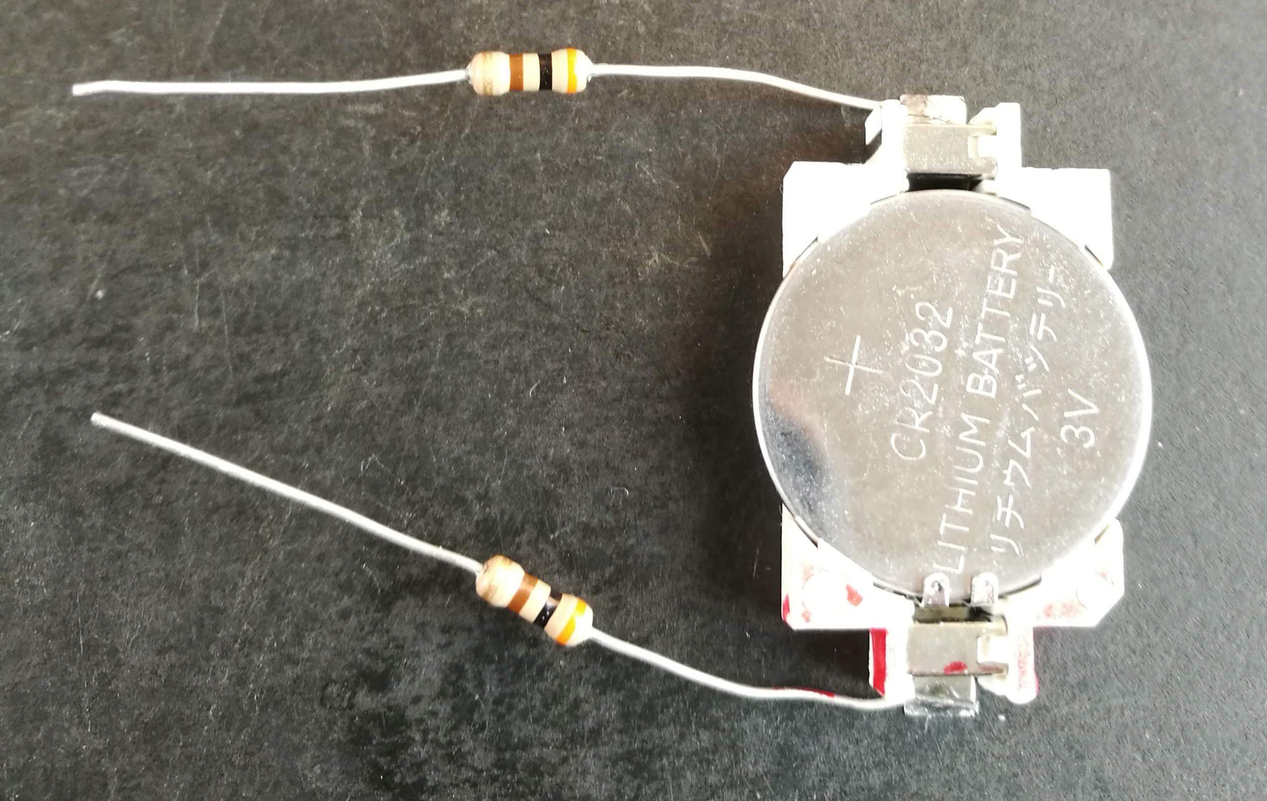
As you can see, the 2018 model was a very clever use of what was on hand. A CR2032 holder powered the probes and the probes themselves were two resistors. If you can get the LED to light with the probes you know which lead is the anode and which is the cathode. A little red ink makes it even more obvious.
Mess with Success
 One school of thought was that these probes worked well in 2018 so we could just build up some more for the 2019 challenge. However, while these worked well enough, they were not very handy to use. The little wires aren’t really springs, and they would fatigue after long use.
I wanted something that would hold up to abuse better and have a little bit better ergonomics. I thought about 3D printing something. As I always do before I try to design something, I did a quick search to see if there was anything similar out there.
Over on Thingiverse, [Tom20170] had just what I needed. It was a simple 3D print for an SMD test clamp. It had a springy little plastic coil, and a housing to hold breadboard cables to use as probes.
Customize
Printing was easy, but I didn’t want to have too many wires or connections, so I wound up making two very simple modifications.
Here’s my bill of materials:
- Eagle Plastic Devices 12BH443B-GR – 4 AAA battery holder with 9 V snaps
- Keystone 237-M – 9 V battery snap with 8″ leads
- 100 Ω resistors from my junk box (see below)
- Molex 02-06-2132 – Crimp pins (only needed for the second version)
- Heat shrink tubing
- Electrical tape
The 9 V snaps were ideal. I got the better kind that has a molded body instead of the cheap ones that tend to break after 9 or 10 snaps. They do cost a little more, but even if you are only buying one they are still under a dollar. Saving fifty cents and breaking the connector every few months is definitely false economy.
I made a few with the Molex pins and decided the resistor leads were probably just as good bare, so I didn’t use the rest of the pins. I used heat shrink on them when I did use them. You could probably also use the wires the Thingiverse design calls for, if you wanted.
The resistors are what I had on hand. They aren’t super critical and if I had to do it over again, they are one of a few things I’d change.
Construction
 I printed a bunch of probe bodies using PLA at 0.3 mm layer height on an ANET A8. I used 20% infill, but that probably wasn’t very important. They don’t take long to print, so I fit as many as I could put on the bed at one time, and then did a few runs.
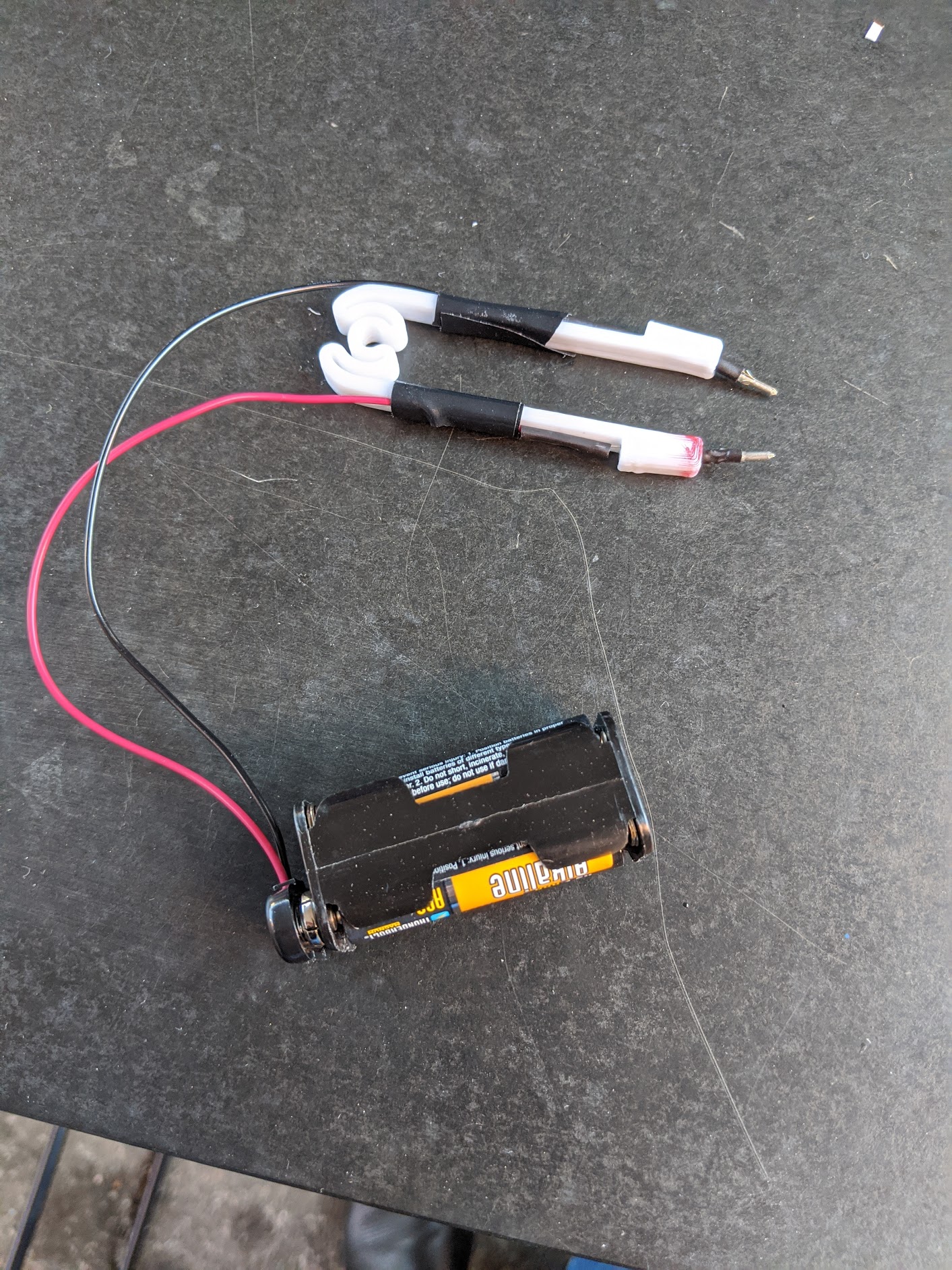
The resistors slot nicely into the cavity on either side and a little heatshrink hides the solder joints. Electrical tape or heatshrink ties the wires to the sides to strain relief everything. As before, a little red ink makes it easy to see which lead is positive.
If you look closely, you’ll see that a permanent marker isn’t the best way to mark PLA. It sort of soaks into places you didn’t mean for it to go. However, for a positive mark, that’s not very important. I wouldn’t use it to color a 3D print, though, if it mattered that the color region was crisp.
More Tweaks?
We couldn’t really tell if anyone preferred the tips versus the bare resistor leads. Having the batteries detachable definitely made it easier to transport the probes.
The resistors limit the current depending on the LED’s forward voltage. Typically, an LED will have somewhere between 1.8 V and 3.3 V drop. With a 100 Ω resistor, that works out to a range between 13.5 mA and 21 mA. That’s a little hot on the high end, and you could probably safely increase the resistor values. With two 470 Ω resistors, you’d have the current run between roughly 3 mA and 8 mA. 1 kΩ should also work, but might be a little dim.
Instead of using a higher resistance, I had toyed with the idea of putting a second LED in series so the tweezers could double as a continuity probe. A 1.8 V red LED, for example, would see about 12 mA if you short the probe, but would still let most LEDs under test to get 5 or 6 mA with a 100 Ω resistor.
The Right Stuff
Of course, if your multimeter has a diode setting, that’s probably the right tool for the job. The positive probe will indicate the anode of the LED if the device lights. If it doesn’t light, switch the probes around.
If you look at the LED datasheet, you should find a way to identify the polarity optically. For example, some have a green stripe, a dot, or a notch. You can also intuit the polarity by noting the connections inside the LED if it has a clear lens. Sometimes the shape of the solder pad will tell you. If the components are on a reel, the reel usually has a way to tell, but that doesn’t help you if you just have a few loose parts.
Have a look at this LED datasheet from Vishay. You can see the terminals and pad look a little different. This one from Kingbright clearly shows a cut-off corner. You can see many examples in this Digikey TechForum post.
If you want to see more about the SMD challenge, check out [Dan Maloney’s] experience. Perhaps you prefer your tweezers a bit smarter. However, if you do make a pair of these, post them up and send us a link. Meanwhile, you can start practicing for next year’s competition. It is never too early.


When you did this for DEFCON, parts datasheets were made available beforehand. I used this to determine 0201 optically. I could easily see the rest.
Using the same title photo as [Dan] made me wonder if a different HaD author was blogging about the same story.
( Not that it has ever happened before B^)