PCB rework for the purpose of fixing unfortunate design problems tends to involve certain things: thin wires (probably blue) to taped or glued down components, and maybe some areas of scraped-off soldermask. What are not usually involved are flexible PCBs, but [Paul Bryson] shows us exactly how flex PCBs can be used to pull off tricky rework tasks.
 It all started when [Paul] had a run of expensive PCBs with a repeated error; a design mistake that occurred in several places in the board. Fixing with a bunch of flying wires leading to some glued-on components just wasn’t his idea of tidy. A more attractive fix would be to make a small PCB that could be soldered in place of several of the ICs on the board, but this idea had a few problems: the space available into which to cram a fix wasn’t always the same, and the footprints of the ICs to be replaced were too small to accommodate a PCB with castellated mounting holes as pads anyway.
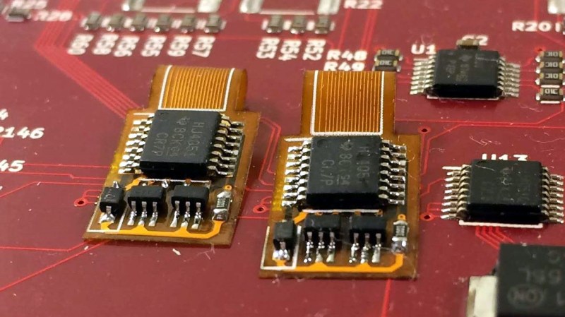
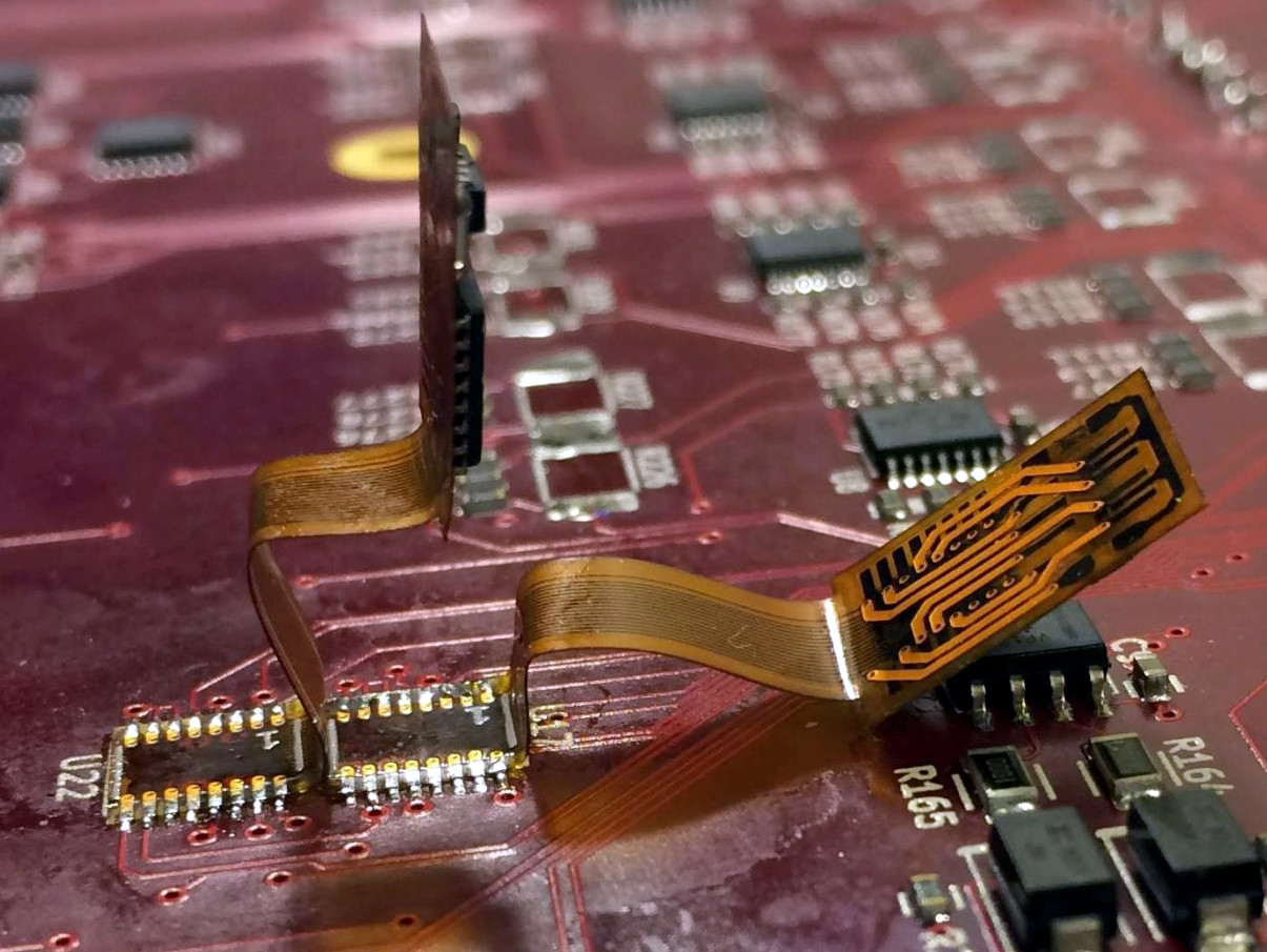
It’s about then that he got a visit from the Good Idea Fairy, recalling that fab houses have recently offered “flex” PCBs at a reasonable cost. By mounting the replacement parts on a flex PCB, the board-level connection could reside on the other end of an extension. Solder one end directly to the board, and the whole flexible thing could be bent around or under on a case-by-case basis, and secured in whatever way made sense. Soldering the pads of the flex board to the pads on the PCB was a bit tricky, but easy enough to pull off reliably with a bit of practice. A bonus was that the flex PCB is transparent, so solder bridges are easy to spot. He even mocked up a solution for QFP packages that allows easy pin access.
Flex PCBs being available to hobbyists and individuals brings out fresh ideas and new twists on old ones, which is why we held a Flexible PCB Design Contest earlier this year. Repairs were definitely represented as applications, but not to the extent that [Paul] has shown. Nice work!


Hey, this should work great for modchips!
It already does.
Nice work, very clever!
“the Good Idea Fairy”
someone who rarely visits me.
B^)
Maybe it’s like the tooth fairy… you’re supposed to leave an idea out sitting on a saucer overnight and find a 1c coin left there the next morning. (Yes, I’m showing my age since 1c coins have been out of circulation here in Australia for decades.)
I’m more interested in the fact that you leave your teeth in a saucer rather than under the pillow. Is this an Australian thing?
Been working on this exact same theory for a mod chip for the Arduboy!
https://community.arduboy.com/t/self-bootloading-mod-chip/8229/45
Hey Kev, fancy meeting you here
Solid work here
Well.. more like flexible work..
+1
What a bloody good idea. I will remember this one for sure.
I feel like an interposer board would have also worked and required less manual labor. You don’t need castellated edges. You just need pads on the bottom similar to how BGA’s mount.
Pads under a board can be a pain to get soldered right or to diagnose in case of failures. The castellated edges, or this way with the flex, allow easier visual and electrical inspection.
It’s the same with BGAs. It’s clear they are reflowing the whole board anyway as you can see solder on unpopulated pads. I’ve had to do an interposer to fix a BGA routing issue, it’s really not a barrier.
It’s more like QFNs
Just give it a wiggle and you know when it’s soldered down properly
But rigid interposers have their own pros and cons and you have to weigh everything out
There is no one size fits all even in something as simple as this
Not reading the linked documents but solely looking at the pictures, someone forgot to put some clamping diodes on signals going into a analog multiplexer chip. I did not know you could make castelated pads on flexable pcb’s.
He didn’t. The pads just come to the edge of the flex. It’s thin enough to solder to the board.
It’s a flex PCB, so one can easily trim or even fold the pads.
You can get analog MUX with some levels of overvoltage protection built-in from the usual chips vendors.
Just google for “Fault Protected analog MUX”.
We made a fix once for the LCD interface on a cell phone prototype design, where we reversed the connections of a zebra connector.
The fix was to make a dual sided flex PCB that was sandwiched between the two mating surfaces to fix the wiring. Worked like a charm.
Hmm, idea here: create flex pcb with footprint for your microcontroller so that voltage and programming pins are routed, cut out square under processor, cut between pads, and BAM, you have flex programmer for unsoldered chips. Just place it on some sponge (so that every trace is pressed separately), press your micro onto board and hit program.
EEVblog #1262 literally put up a tutorial about how to do this a month ago.
cool concept!
You would not even think about doing this just a few years ago but now that you can get dozens fully populated flex PCBs in a couple of weeks for a couple hundred dollars you would be dumb to respin a bunch of prototype populated boards for something like a messed up layout or part swap in most cases
I did my first flex PCB modwork in the summer and the eevblog did a video about it last month
I’m even considering making one to put a more powerful processor on a board I’m doing firmware design on so I have more headroom to experiment before cutting code down to size, and another one to breakout the programming interface on the actual processor and eliminate development prototypes all together and all the problems they cause
What a time to be an engineer
When do we get our desktop flex PCB printers? :P
Let’s hope you don’t have to rework the rework boards!