It’s the [Bruce Land]-iest season of all, when the Cornell professor submits the projects his microcontroller class students have been working on all semester. Imagination does not seem to be in short supply with these students, and we always look forward to these tips this time of year.
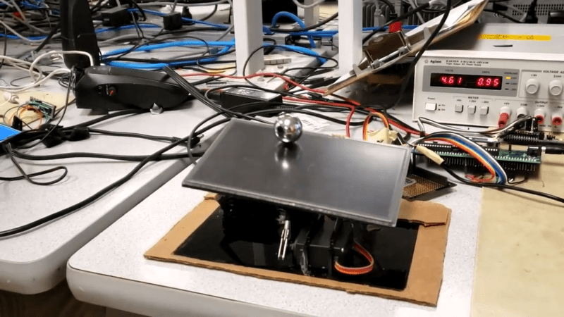
[Greg] and [Sam]’s touch-screen two-dimensional ball balancer is a good example of what [Land]’s students turn out. The resistive touch screen is supported by a 3D-printed gimballed platform and tilted in two axes by hobby servos. [Greg] and [Sam] chose to read the voltage outputs from the touch screen directly using the ADC on a PIC32, toggling between the two axes at 2 kHz. Two PID control loops were implemented to keep the ball as centered as possible on the platform, and the video below shows that there’s still some loop tuning to do. But given the positional inaccuracies of hobby servos and the compliance in the gimbal, we’re impressed that they were able to keep the system under control at all.
Of course we’ve seen ball-balancers before, but most of them have closed the loop using either cameras or microphones. Seeing direct sensing on the platform like this is a nice change of pace.


Nice, though it bothers me immensely that the psu goes into constant current mode, it might even be contributing to the instability.
Quite neat. This is not an easy control task.
I wonder if, as is, it would be more stable with a supply that isn’t going into current limit mode when the servos run.
Using a smaller mass (ball bearing) would probably helps as well due to the smaller velocities and the less extreme movements required to control such a mass.
Its almost as if this is one of those projects where the electrical students need to team up with some mechanical students to create the final project.
Maybe they tried and saw that the resistive panel is not precise enough for a smaller ball.
A larger ball is easier.
Your control challenge is minimising error. Your servos will have movement error, and your sensors (the touchscreen) will have error, and both will have lag. Minimising these minimises the perturbations in your system, which transfer to the mass via movements of the panel through the servo arms and the acceleration of the ball. Unfortunately, those are fixed on selection of components, so only knobs to tweak are the control loop, and the moving mass. Assuming the control loop is properly tuned (a nod to my main man Kalman) that leaves the mass. A larger mass accelerates more slowly for a given panel displacement, so latency in measurement and response has a smaller effect on overall error.
It’s the same reason why balancing a broomstick on your palm is easy, but balancing a toothpick is not.
>But given the positional inaccuracies of hobby servos
Sounds like someone doesn’t know how the feedback works. The PID loop should be able to offset “inaccuracy” as it uses the actual position of the ball instead of relying on absolute servo position. All it does is to increase/decrease *relative* servo arm angle.
Not really. If the servos and mechanical system have slop / play in them (and they do) then you have large non-linearities in the loop that make the control task much more difficult. If you want the control system optimized now you have to deal with dead-bands. Much tougher. I would like to see how this thing operates if there were springs added to the table to eliminate all of the play in the system. I bet it would be a lot more stable.
Maybe they meant an issue with the positional resolution?
inaccuracy =/= resolution as something can have very high resolution but shitty accuracy e.g. non-linear pot for the position feedback inside the servo. There are much better servos than your typical $2 Chinese ones.
The amount of dead band in the servo could limit the amount of minute adjustment that can be made in the short term – i.e. a minimum step size. It is not like these servos are well tune compared to the ones I played with in my high school RC days.
The PD should be able to keep the system balanced even with low servo resolution. The I term in the PID would push for a large enough adjustment step for the servo eventually if the ball while stable is off center.
I wonder if it would work better if they didn’t keep hitting the current limit on their five Volt power supply and having it fold back.
It certainly would have made tuning the control loop easier if they’d had a stable voltage. No wonder it took “about a quarter” of their project time to tune.
Definitely a neat idea. Next step, drive the display, showing Pong.
https://www.youtube.com/watch?v=j4OmVLc_oDw
Nothing new here
Quite nice for a microcontroller class but for a control engineering class I would consider this a fail ;-). What doesn’t really help is the placement of the servo arms relative to the touch screen. It makes the relation between servo angle and touch screen angle non-linear which is never good for control loop stability. Proper system analysis and control loop design would also help a lot to improve performance, compared to manually trying to fiddle with parameter. But that’s probably out of scope of this lab exercise.
Here is a very similar project from 2014 that hackaday.com convered. Even uses a resistive touch screen.
https://hackaday.com/2014/08/22/stewart-platform-ball-bearing-balancer/
That’s more the stability I was expecting.
It could be entertaining to run your fingertip around on it instead of a ball.