With Tormach and Haas capturing a lot of the entry-level professional market for CNC machines, we don’t see too many CNC conversions of manual mills anymore. And so this power drawbar conversion for a Precision Matthews mill really caught our eye.
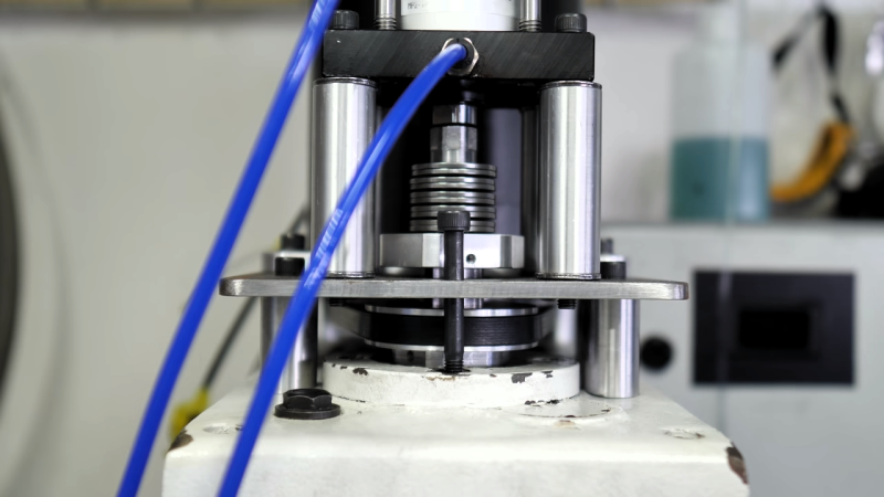
What’s that, you say? Didn’t [Physics Anonymous] already build a power drawbar for a mill? They did, and it was quite successful. But that was based on a pneumatic impact wrench, and while it worked fine on a manual mill, the same approach would be a bit slow and cumbersome on a CNC mill. For this build, they chose a completely different approach to providing the necessary upward force to draw the collet into the collet holder and clamp down on the tool: springs. Specifically, Belleville spring washers, which are shaped like shallow cups and can exert tremendous axial force over a very short distance.
[PA] calculated that they’d need to exert 2,700 pounds (12,000 Newtons) of force over a length of a couple of inches, which seems outside the Belleville washer’s specs. Luckily, the springs can be stacked, either nested together in “series” to increase the load force, or alternating in “parallel” to apply the rated force over a greater distance. To compress their stack, they used a nifty multi-stage pneumatic cylinder to squash down the springs and release the collet. They also had to come up with a mechanism to engage to machine’s spindle only when a tool change is called for. The video below details the design and shows the build; skip to 11:32 to see the drawbar in action.
We’re looking forward to the rest of [Physics Anonymous]’ conversion. They’re no strangers to modifying off-the-shelf machines to do their bidding, after all – witness their improvements to an SLA printer.


I did this myself a long time ago, and made a spreadsheet to work out the force / displacement for disc springs in stacks of between 1 and 4.
https://docs.google.com/spreadsheets/d/1_JIG00w1hZ_2KD9WWh3XonWUI20ZkZ1S3nBAszeeYqw/edit?usp=sharing
I was lucky in that there was space in the drawbar tube for the springs.
(Blimey! Was it really 9 years ago?)
https://www.youtube.com/watch?v=pxrzJ_KfcQ0&t=7s
That is a cool idea. If it can be miniaturized then it could albo be used as a quick-release for toilet seat. This way you could have multiple toilet seats. When one gets covered in feces you can qucikly put in another one. The dirty one can be then pressure washed in a car wash.
Your absurdist deadpan made me laugh
And it opens up the market fo tdd BYOTS, bring your own toilet seat. Rids the environment of those useless seat protectors
I am not a machinist, but I do have some engineering education. At 6:43 in the video I’m getting screaming alarm bells, as my GELP ( Good Enough Limit Point) is not being met. The channel for that clip looks decidedly non square and the clip appears to be bottoming out on it’s inner corners. This has seriously colored my view of the rest of the build and I’m seeing No-no’s everywhere, now.
If you are a machinist, please chime in. Does my GELP need recalibration, or is this a house of cards built on a Jello foundation?
It seems like a great plan in concept, but I’m cringing at some of the execution.
I am a machinist, but I tuned in shortly before that, to my horror- when I saw him use an unsheilded lathe with a right angle grinder. I recoiled in horror.
1st of all, hes running his lathe probably too fast for grooving- though hard to tell with camera speed effect. I saw him shatter a carbide cutoff tool before that.
Use high speed steel for interrupted grooving man, before resorting to grinding. And for gods sake, shield your ways and everything before you grind on a lathe!
I know, I know, I sound like a know it all ass, but I am a machinist. I cry when I see people abuse good machine tools like that, even when I applaud their ingenuity.
Your concern- probably unwarranted. Took a look- I think you are just seeing play in his components.
Hatd to tell that level of accuracy from a vid, but keep in mind that spline appears to be milled, and probably made in China.
What will happen is the aluminum block will get worn into in one orientation by the steel circlip and the surfaces where they meet will gradually become more paralell as they wear together. But because the spline shaft is keyed to the aluminum sliding block, neither will rotate with respect to each other to do that much.
I havent watched enough to see how the entire thing works, but I have used enough mills with power drawbars to guess. Itll be fine. Some play on this is a good thing- but more on the circlip groove so it orients flat to the block, which will never move. If it were me, I would have bored an oversize counterbore where it met the circlip, press fit a bronze washer there, and machined the spline hole with it- to create a replaceable wear surface for the circlip to hit against if it need it for later repair.
Dont think any of that matters here though.
Engineers- I am one in a sense because I design my own tools, tooling, fixtures, and machinery too- but they often overthink uncritical things, and underthink critical things on stuff like this :)
So you copied the Haas design. Not new.
Except Haas isnt going to publish a how-to video on how they made theirs.
And many might not have ever seen a professional version, so this helps them make one to retrofit their own mills, which don’t have this.
Your right, i was in a bad mood when I posted that and regretted it shortly after. Sorry, I tried to delete it.
I’m a former Haas tech and I’ve had a number of drawbars out and realized after the fact most folks probably never saw one apart.
It’s also exactly how the Tormach drawbars work.
Pneumatic piston pushes down for release, springs push up to hold.
This is why we need TTS or BT20 and other such tool holders — R8 collets need rotation to change out because of the threads.
Could screw drawbar knobs into the R8 threads, same as is done with other holders for linear pull drawbars.
2700lbs of drawbar force sounds a little steep for an R8. Fadal is around 900-1500 for CAT40 and HAAS is in a similar range. When you get to really fast spindles the force goes up to keep the tool absolutely clamped.
I wouldn’t expect you need more than about 1500lbs on an R8, given that when you’re torquing a manual drawbar the brake on the bridgeport and length of the wrench is a limiting factor. I don’t think I torque to more than 40 or 50 ft/lbs and that’s fine.
I explored this a while ago but here is what I came up with…
Since CAT40 has drive lugs to transfer the torque, the taper itself only has to locate and support the tool…meaning that you can have a lower drawbar force.
In an R8 there is no drive lug (the pin is for indexing the collet), so the taper also has to transfer the torque…and it requires a higher drawbar force.
You can pretty easily calculate the drawbar force if you know the thread and torque spec. For an R8 it’s a 7/16″-20 and I would typically expect 20-30ft-lbs of torque…this works out to 2700-4100lbs of force.
So interestingly enough 2700lbs is just barely enough and realistically you would want to be over 3500lbs.
Isn’t there a mechanical advantage? Say the threads are 20 to an inch. You do a quarter turn (move drawbar 10 thou) with a 12 inch wrench. You can multiply your force on the wrench by 240?
Belleville’s are use in commercial CNCs too. Just the prong packs were much bigger.
I tried this probably 10 years ago using the tormach tooling system and it was just a failure. Could it get enough tension on the drawbar through Belleville’s to get good tool retention. I scrapped it all in favor of getting a 30 taper spindle and a Maxi Torque Rite power drawbar. That thing is fast.
For what it’s worth, the “small displacement, but enough if you stack them” paradigm is how piezo fuel injector nozzles and several other devices work.
Anyone getting tired of Wordless Workshop videos? Especially with Outerbaijanian Rave-Pop music?)
You had me at being tired of videos, but I guess I’m old. I miss solid write-ups with pictures, drawings, charts of test results, etc. Most videos are poorly done, largely unscripted, and just plain painful.
If you’re trying for a multilingual audience, it has a lot of advantages. I’ve seen a lot of videos where essential information was in Russian.
The thing about wordless (the old cartoon in every issue of popular science) is you don’t see the plan or goal in any useful form beforehand. Watching people hacksaw and bend stuff and weld and grind becomes quite a waste of time. Even when they are as entertaining as This Old Tony (most of his are loaded with good info, so…) or Colin.
Belleville washers are amazing. I’ve used them as engine mounts, capturing, on both sides, the mount itself, and in machines as adjustable shims. They’re cheap, and there are plenty of online calculators for converting a big bucket of them of known calibration into just about any deflection force or range you want.
Cool, but I’m not sure why this is news. Guys were doing this to their Harbour Freight benchtop mills 15 years ago.
Look this up on the wayback machine: http://www.hossmachine.info/projects_7.html
A company called Zbot took Hoss Machine’s design from 15 years ago and made it into a retrofit for the chinese machines:
https://littlemachineshop.com/images/gallery/Instructions/2936PowerDrawbar.pdf
http://springipedia.com/belleville-washers-stacking.asp
Does the author has “series” and “parallel” descriptions flipped?