When it comes to testing power supplies, it’s useful to have a dummy load to put the gear through its paces. While it’s possible to just use some old heating elements or other big resistors, an active load can provide more control over the process. [Charles Ouweland] found himself in need of just such a piece of gear, and decided to build his own.
Commercial units often pack in a raft of features, operating in different modes from constant resistance, constant power, and constant current. For [Charles]’s needs, just constant current would be fine, and thus the design progressed around this constraint.
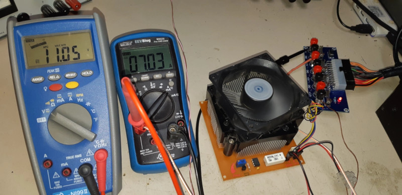
The IRFP250 MOSFET specified in the build can dissipate up to 190W, but as it heats up, this is reduced. In this design, cooled by a heatsink and PC fan, [Charles] estimates 120W continous output is a safe limit. It’s combined with an LM358 op-amp and TL431A reference voltage source to act as a current sink, controllable between 0 and 10 amps.
We’re sure that the new hardware makes testing power supplies a cinch for [Charles], and it’s always good to have a strong understanding of the workings of your own test gear. We’ve seen open-source designs in this space, too!


that pcb design makes me feel bad :(
A reminder from your favorite hacker villain…
https://www.youtube.com/watch?v=p2_lJ2bGltE
Yep. One of the main loads I use pretty much a small bank of various light bulbs. Works pretty well. But another I quite like has been a balanced circuit made of a double transformer. You redirect the flux one way or the other. So it acts like an amplifier and a current limiter, seems to work pretty well in place of a variac or liquid variable resistor.
Indeed. For those of us in north America with the screw sockets, for 115V it’s quite handy to grab a multi bulb fitting intended for over a mirror or one of the fuse blocks out of the top of an old stove with an array of sockets. Then get filament lamps of binary-ish values x10 plus or minus 10 percent, and have 160ish, 80ish, 40ish, 20ish 10ish watt bulbs (You can use LED for the low consumption end if you want to waste energy more efficiently ;-) ) then you can just have them in loose and “dial a load” by tightening them up and down with a pan holder or oven mitt.
For lower DC voltages you can use automotive bulbs, but finding such a ready made holder is more difficult, so you might end up doing a lot more wiring and fab to make one of those. Bear in mind that when you replace headlamp bulbs or stop-&-tail bulbs often it’s just one of the filaments burned out, so you can save those as 50W or 20W loads at 12V. Recalculate for other voltages.
Automotive Headlamp bulbs work pretty well for loads. The cold in-rush curent is about 5X the operating current though.
Active loads generally don’t start up gracefully as the input voltage ramps up. The ones that I have worked with tend to overshoot the current setpoint by a large margin (3X to 5X) for a short time when they do come on.
I’m planning on using a headlamp bulb as the load for the 5v rail on a ATX PSU conversion. It’ll be bulky but it’ll work :)
The cold inrush current is much more then 5x nominal: It’s at least 10 times. Or even 15 * in very cold environment.
If the input voltage of an electronic load _ramps_ up, it normally works fine. But if it is switched on externally, like with a slope of about 30 to 50µs, you get huge peaks.
@geocrasher: Check if you really need a baseload like in the old days of AT PSUs. The ATX PSUs I had tested started all up without an extra load.
I designed an active load bank for switching power supplies for the military many years ago. As a junior engineer, I thought the design (very similar to your concept) was very good. However, testing proved otherwise.
The power supplies we were testing required that we soft start the loading as the power supply sensed the loading as a short when it was first turned on.
Secondly, from time to time, the load would oscillate. The follower configuration was not very ‘hardy’ in the sense of stability. Mostly, things were stable, but occasionally the instability would arise and there would be over currents on the ps output. Granted, the active loads for many PS outputs were all common grounded through a big bus bar.
Lastly, I was looking through an old textbook (the art of electronics) and the authors indicated that the follower topology for loading was NG.
Just my experience. I don’t think the active load circuit we built was ever 100% stable.
A word of advice… Using a switching FET like IRFP250 for linear power dissipation is not good practice.
I made an electronic load exactly like this not long ago. The FET kept blowing up despite it never reached anywhere near rated power dissipation. It turns out that switching FETs are not rated for linear operation for a reason and those FETs that are rated for linear is way more expensive :-(
What happens is that across the silicon, some areas might conduct slightly better than others resulting in local heat increase. This lovers Vgs for that area causing even more localized heating i.e. localized thermal runaway beyond destructive levels even though the overall power dissipation is below the specified rating of the device.
Interesting, thanks, do you know if that applies backward? i.e. push a linear rated part above it’s linear rated dissipation in switch mode?
I know it’s a “you shouldn’t” but I always find my way to edge cases, through leveraging contents of junk pile and existing component stash etc.
That’s what the SOA curves in the datasheet are for. They tell you the amount of V*I vs the time allowed for the part. There are also a couple of graphs covering single pulse rating and duty cycles for the transient thermal impedance. Ignoring those are exactly why they blew up.
I should probably start using newer parts. I’m used to seeing one blodgy graph possibly hand drawn with a chisel tip sharpie at postage stamp size in the first place and faxed, photostatted, and scanned a dozen times before it got on the web.
A good ol’ TO3 or TOP-3 bipolar would probably be better.
Careful of fakes. Some use a smaller die and don’t have good thermal transfer from die to case. With TO3 you can cut the top off on in a batch to check.
I read an application note that said to never use current ratings of a mosfet, only use the RDSon, the switching capacitance and times, and the package to case thermal resistance, and calculate it from that. And then it doesn’t matter what type it is labelled as.
The other numbers are usually only talking about the semiconductor device, as calculated from the physical properties, without considering the package.
I am kinda curious if people actually use electronic load a lot? I have only used an electronic load may be 4 times in 10+ years. The last 3 times I use one are for dynamic test i.e. a load that pulses quickly to test power supply transient response.
Most of the ones I have seen on HaD only do static load and not too useful beyond a torture test or as a discharge load.
The thing is if you need a load most are better off scrounging than buying.
You aren’t likely to have power resistors, especially at low enough ohms to load a high current supply.
I know I’ve thought about taking a switching supply and using the power transistors or FETs to make an active load.
The switch mode parts are wrong type for static loads as they optimize for low switching losses (low capacitance) and low switching resistance. Low loss means that they can get away with smaller dies. SOA won’t be useful for high current at high voltage. You would want ones that come from large linear amplifiers.
My point is that I rarely need a load and when I do I need a dynamic load not a static load. For dynamic loads, I can switch at duty cycle of 1% and get away with much smaller heatsink and can use the switch mode FET (smaller dies). I have a lot more resistors than linear FET.
I use one 8 hours a day 5 days a week. We design LED drivers, and we have special fancy loads that emulate LED’s. I think most power supply people have electronic loads of some sort, as do most automated test engineering people.
The usual HaD constant current loads aren’t exactly what you or any of the example usage. The people building them are exactly into those areas either.
I do stick my head doing power supply stuff as most of the time no one else want to or qualified to do it. I use dynamic loads to test transient response. At one point I want to select power supply modules for an embedded processor. I had to make my own tester that simulates the processor with 100A/us load pulses. The hp load could only do 25A/us (or was it 50?).
Even just for DIY LED drivers a load is really useful.
Have designed and built many electronic loads over the years (huh, do not really know, probably at least 50), many of which used transistors not intended for linear operations. Many of the linear designs used bipolar transistors where low compliance voltage was not a big issue. Use of ‘non-linear’ devices is ok if you carefully control the SOA; which the design in this post does not. If you have good gate drive you can parallel transistors.
As most of my designs were one-off special purpose stuff that operated over a narrow range so issues such as reliability, loop response to transients and load voltage changes were easily controlled. In general, used decent op amps (the LM358 sucks), and lo-noise voltage references and components with decent temperature coefficients. And you really need a few nF between the gate drive the the current feedback signal.
IRFP250 does not have a specified DC SOA. It is normally not a problem and a lot of professional companies design electronic loads with such parts (most BK precision models, HP 6060B to name a few examples) BUT transistors are operated at around 35W per piece, not 120W. Both SOA and thermal specifications need special attention and adequate derating to keep reliability reasonable.
As far as linear mosfets being much more expensive, this is not always true. You can get more bang for the buck after derating. Also there are plenty of parts cheaper than IXYS ones. Few months ago I was looking for a DC rated mosfet myself, my optimal picks in terms of SOA/$ for that application were: FDL100N50F, AOK60N30L
Thanks for those type numbers. The SOA graph in the FDL100N50F’s datasheet indeed includes a DC line. But the SOA graph for the AOK60N30L is unclear: it includes a 100ms line but under that line it just says DC without a line. Makes no sense to me.
I have a design I’d like to clean up, but I’m putting the idea out there for people who are more talented at getting projects assembled: make a grid-tie eload. Sink your power into the grid. Then you can dump 1700W with almost no heat issues. Obviously there are some safety issues of not electrocuting someone if the grid’s down and people are working on it, but realistically, if the grid’s down, so is your test system.
That’s basically gonna be a solar grid tie install so $5000 for the certified equipment and certified installers to be allowed to hook it up.
If the source is from the mains itself (e.g. no external energy sources like solar panels or batteries), there will not be a net export to the grid. That said, it would probably be a lot easier to make it a combination power supply/load.
In Oregon they let you do it yourself, and the certified equipment includes all the reputable brands including the cheap ones.
You can put whatever you want on the other side of the inverter.
Allowed? To Plug something into the mains socket? Just don’t ask too many questions, then you avoid getting unwanted answers.
But you also can buy electronic loads and 4 quadrant power supplies which pump the excess power back into the grid.