Gears are fairly straightforward way to couple rotational motion, and the physics topics required to understand them are encountered in an entry level physics classroom, not a university degree. But to really dig down to the root of how gears transfer motion may be somewhat more complex than it seems. [Bartosz Ciechanowski] put together an astonishingly good interactive teaching tool on gears, covering the fundamentals of motion up through multi-stage gear trains.
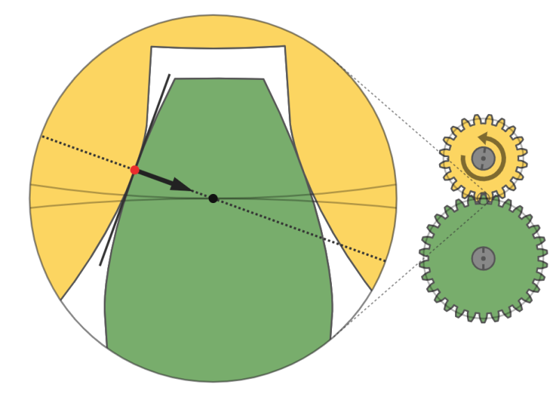
The post starts at the beginning – not “how to calculate a gear ratio” – but how does rotational motion work at all. The illustrations help give the reader an intuitive sense for how the rate of rotation is measured and what that measurement actually represents in the real world. From there [Bartosz] builds up to describing how two discs touching edge to edge transfer motion and the relationship of their size on that process. After explaining torque he has the fundamentals in place to describe why gears have teeth, and why they work at all.
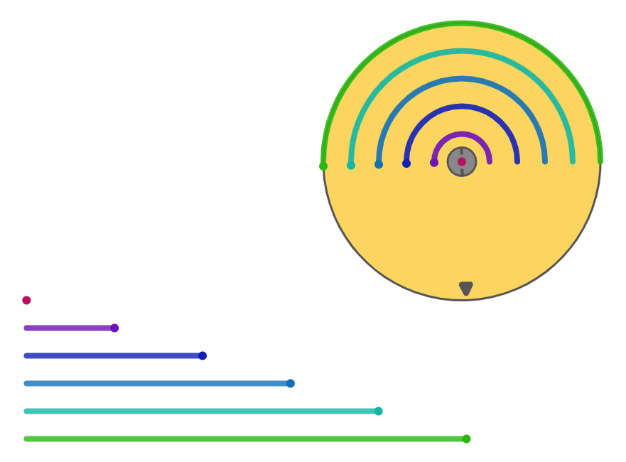
Well written explanatory copy aside, the real joy in this post is the interactivity. Each concept is illustrated, and each illustration is interactive. Images are accompanied by a slider which lets you adjust what’s shown, either changing the speed of a rotating gear or advancing the motion of two teeth interlocking. We found that being able to move through time this way really helped form an intuitive understanding of the concepts being discussed. This feels like the dream of interactive multimedia textbooks come to life.


Very well done, though I would prefer to have the animations stopped and being activated by the user. Otherwise it is too distracting while reading the text.
“By default the animations are enabled, but if you find them distracting, or you want to save power, you can globally pause all animations”
2nd paraagraph
He was too distracted by the animations to read that.
May be it’s something that’s recently added after the article is featured on HaD, but currently each animation has a big pause/play button prominently featured.
Lol, probably.
There is that option.
“This feels like the dream of interactive multimedia textbooks come to life.”
Indeed. So much better than a YouTube video that needs sound to be playing, has a person waffling on in monotone voice, and no ability to easily flick through and find the bits you are interested in.
I can see it might have taken far longer to produce though! I wonder what tool was used to produce the animations?
Are very large gears’ teeth equipped with rollers or balls? From the zoomed-in picture it seems there is inherent sliding, and hence friction, involved in gear movement.
For primitive gear tooth patterns there is a lot of friction. For involute profiles the tooth surfaces effectively roll on each other and reduce it to a minimum.
Always remember- 99% of gears in world are involute tooth form- designed for smooth motion and efficient torque transfer.
But the gears in horology (watches and clocks) use another tooth form called cycloidal gearing. Cycloidal gears are also used in gauges like dial test indicators and measurement devices- they are designed for efficient torque transfer, but mainly extreme accuracy of angular movement, needed in devices that use gear rotation for actual measurement. They have a lot less backlash too than involure gears, where thats normally not a concern.
*(theres also crazy exotic tooth forms from companies in horology like Agenhor, but I’m not even touching that stuff)
The more you know :)
Actually only real function of the gear train in horology is to transfer torque from the mainspring. Once the energy reaches the escapement wheel, all angular reference would be lost anyway. Watch hands only need to be consistent over a 360 degree cycle. The prevalence of cycloid gearing is a combination of ease of manufacture for really tiny gears, gear strength at small tooth counts and the fact that mechanical watch making was a deeply conservative industry when involute profiles were first being considered and now makes a fundamentally obsolete technology where small efficiency gains are no longer a driver of greater sales and deep tradition is.
In horology- you are correct- gears are normally only for efficient torque transfer.
The part though about angular accuracy and minimum backlash was meant mainly for indicator class devices.
Tooth strength is ironically stronger in involute gearing, from what I know, due to truncated tooth design.
I fail to understand though what, in either form, makes one more “difficult” or “easy” to manufacture. They are inherently created in all the same ways at all sizes, perhaps older brittish standard with flat tooth roots is easier to make the cutters for, and that’s it.
I am not, however, an expert on gearing, though I do have formal training on their calculation for creation for restoration. Gearing is a pretty complex subject, and I’d love to hear more from any experts out there as to why cycloidal is still used in timepieces long past the invention of involute, beyond the catch all “tradition”. I’ve never heard a convincing answer to this actually.
This is absolutely true and has been the focus of gear design and a lot of tribology & lubricant development for a couple of centuries. The “rollers” are usually at the molecular scale for any real load-bearing gear train since burying them in slippery goo is a heck of a lot simpler than a zillion tiny roller bearings. The smallish gears you see in widgets, servos, a lot of consumer goods, and other fun applications usually rely on low loading and the relatively low friction of thermoplastic (often nylon), brass or powder-molded metal gears.
I would imagine you’d have to factor in lubrication which will perhaps act as a bearing.
Maybe hackaday should write a tribute article about Springfield Vermont and all of the interesting technology that was pioneered there, including the Fellows Gear Shaper.
Thailand you very much. I scannten across your article and marked it for the weekend to be read in detail.
Further reading on sliding motion and friction, different type of teeth would be appreciated.
Good work,
Chapeau
Gvtt