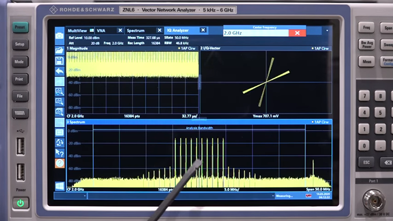
[The Signal Path] snagged a fancy Rohde & Schwarz vector signal generator that can go up to 3.2 GHz, but sadly it wasn’t in working order. It powered up and even put out a 1 GHz signal, but the amplitude output was very wrong. Interestingly relative changes to the output were correct, it was just that the absolute output amplitude was off by quite a bit and changed with frequency. That started a detective job which you can follow along in the video below.
The instrument is pretty high-end, and did not report any problems even during self-check. This implied that all the internals were probably good and whatever was wrong probably lay close to the output. The service manual’s block diagram wasn’t terribly useful, especially given that all the processing portions appear to work well.
This is a good excuse to just look at the inside of this well-built instrument. Given that the output amplitude changes with frequency, a good guess can be made that the issue will involve some component or components that involve a reactance either on purpose or due to some failure mode.
The obligatory cat didn’t seem to have much of an opinion besides finding the instrument a satisfactory perch. Tracing through the output shows some fast diodes to sample power and trigger a reverse power protection relay. Those diodes were easy to see through their transparent cases via optical microscopy.
As it turned out, the MOSFET controlling the relay was always holding the relay off, and replacing the MOSFET restored normal operation. We don’t think of a relay as a capacitor, but a tiny relay in the off position does exhibit capacitance at these frequencies. Had it been on as it should have been, there should have been no attenuation of the output. But because the failed MOSFET kept it open, it provided a capacitive path that reduced the amplitude of the output signal.
We like opening things up just because, but when we can’t do it ourselves a video of someone else doing it is nearly as good. Test equipment might be our favorite, but old stuff is fun, too.


Niiiice. I love stories about getting expensive but non-functional equipment, and repairing it.
Yes. Though I like it even more when it’s ME that squires the nice bit of expensive test gear :-)
That is always better :-)
I am always amazed that these absurdly expensive pieces of test gear (approaching 7 figures original price) are so often taken down by such minor components. In this case it was the mosfet that drives a relay coil… If I had to hazard a guess it was probably due to the lack of reverse diode on relay coil to prevent the back emf from being dissipated as an avalanche breakdown in the drive mosfet. How did such a simple engineering mistake get overlooked?
The intern did that bit.
But was it “dated” so tgey simply didn’t bother with repair?
I don’t know, this stuff wasx too expensive to be within view.
My guess is that repairing it themselves would remove certifications.
I think most common way to make this mistake is to consider the MOSFET internal parasitic diode sufficient. It some cases it is, but in some configurations its direction actually does nothing to dissipate the back-EMF.
I just ran into this on a colleague’s design. The MOSFET parasitic diode is across the MOSFET, while the relay diode is across the relay coil. The MOSFET diode isn’t going to do what the relay diode does, and the MOSFET will see the relay flyback voltage on its drain terminal, which would be a Bad Thing.
Maybe had the prototype use one part, and production engineering go “Oh, this other MOSFET has exactly the same numbers and is a third the cost” or more convenient package or something.
Yeah I’m sure a company that makes equipment this complicated and expensive simply forgot the reverse diode.
I wonder what it would take to get the hardware to run at 6Ghz. Maybe just aa case of changing the software key.
Probably is as simple as that since it says 5MHz-6GHz above the screen of the VSG. But VSGs are usually used for frequencies 2.45 GHz and below so this guy probably don’t need 6GHz.
Awesome video! Who makes the RF relay shown in this video?
Makes for more inventory turns that drive the development and deployment of the latest and greatest model(s)? Then a bonus for those that wanted one… of course until this video came out and the price shoots through the roof as Shahriar even has noted in other videos… like with Dave from EEVblog. :-|)