Everyone Needs A 1950s Signal Generator In Their Life

At Hackaday, we comb the world of tech in search of good things to bring you. Today’s search brought up something very familiar, [Jazzy Jane] has an Advance E1 tube signal generator, the same model as the unit on the shelf above where this is being written. It’s new to her, so she’s giving it a teardown and fixing any safety issues before powering it on.

For a 70+ year old unit, the quality of these instruments was such that they remain useful and reliable to this day. Unsurprisingly a few things need looking at, such as an aged mains lead and a pair of filter caps in the power supply which haven’t aged well. These parts failed on the E1 here too, and while she’s taking the time to order appropriate replacements we have to admit to being cheapskates and robbing parts with an appropriate working voltage for ours from a nearby PC power supply.

Where this one becomes rather interesting is in an extra switch and socket. It’s a wafer switch with a load of capacitors, and the best guess is it provides some adjustability for the inbuilt audio oscillator which had a fixed frequency on stock models. This is part one of a series though, so we’re looking forward to finding out its purpose in the next installment. Take a look at the video below the break, and if that’s not enough, we seem to have had more than one piece of vintage British test equipment here of late.

Continue reading “Everyone Needs A 1950s Signal Generator In Their Life”

Schematic of the Pi Pico wireup, showing the various outputs that the firmware will generate on the GPIOs

A Scope Test Tool You Can Build With Just A Pico

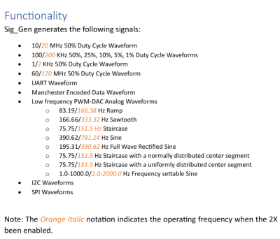
Ever wanted to see how well your oscilloscope adheres to its stated capabilities? What if you buy a new scope and need a quick way to test it lest one of its channels its broken, like [Paul Wasserman] had happen to him? Now you only need a Pi Pico and a few extra components to make a scope test board with a large variety of signals it can output, thanks to [Paul]’s Sig Gen Pi Pico firmware.

description of the signals generated by the software, that can be read in detail on the project websiteDespite the name it’s not a signal generator as we know it, as it’s not flexible in the signals it generates. Instead, it creates a dozen signals at more or less the same time — from square waves of various frequencies and duty cycles, to a PWM-driven DAC driving eight different waveforms, to Manchester-encoded data I2C/SPI/UART transfers for all your protocol decoder testing.
Everything is open source under the BSD 3-Clause license, and there’s even two PDFs with documentation and a user manual, not to mention the waveform screenshots for your own reference.

It’s seriously impressive how many features [Paul] has fit into a single firmware. Thanks to his work, whenever you have some test equipment in need of being tested, just grab your Pico and a few passive components.

Nixie clock from a frequency counter

A Nixie Clock, The Hard Way

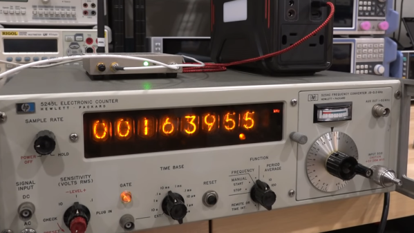
Notice: no vintage Hewlett Packard test equipment was harmed in the making of this overly complicated Nixie clock. In fact, if anything, the HP 5245L electronic counter came out better off than it went into the project.

HP 5245 hand-wired backplane
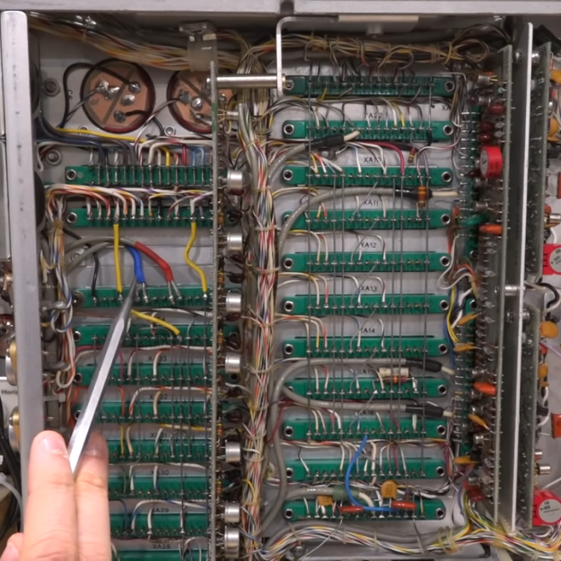
Beautiful hand-wired backplane in the HP 5245 counter.

We mention the fate of this instrument mainly because we’ve seen our fair share of cool-looking-old-thing-gutted-and-filled-with-Arduinos projects before, and while they can be interesting, there’s something deeply disturbing about losing another bit of our shared electronic heritage. To gut this device, which hails from the early 1960s and features some of the most beautiful point-to-point backplane wiring we’ve ever seen, would have been a tragedy, one that [Shahriar] wisely avoided.

After a bit of recapping and some power supply troubleshooting, the video below treats us to a tour of the Nixie-based beauty. It’s a wonderful piece, and still quite accurate after all these decades, although it did need a bit of calibration. Turning it into a clock non-destructively required adding a little bit of gear, though. Internally, [Shahriar] added a divide-by-ten card to allow the counter to use an external 10-MHz reference. Externally, an ERASynth++ programmable signal generator was used to send a signal to the counter from 0 Hz to 23,595.9 kHz, ramping up by 100 Hz every second.

The end result is the world’s most complicated 24-hour clock, which honestly wasn’t even the point of the build at all. It was to show off the glorious insides of the counter, introduce us to some cool new RF tools, and as always with [Shahriar]’s videos, to educate and inform. We’ve always enjoyed his wizardry, from his look into automotive radars to a million-dollar scope teardown, and this was another great project.

Continue reading “A Nixie Clock, The Hard Way”

This Frequency Generator Knows How To Get Down

What kind of clever things could you do with a signal that had a period of 2 hours? Or 20? Any ideas? No seriously, tell us. Because [Joseph Eoff] has come up with a way to produce incredibly low frequency signals that stretch out for hours, and we’d love to figure out what we can do with it.

To be fair, it’s not like [Joseph] has any ideas either. He thought it would be an interesting project, and figures now that he has the technology, maybe some application will come to him. They say that if you’ve got a hammer everything looks like a nail, so maybe the next project he sends our way will be a sinusoidal fish feeder.

[Joseph] says doing the software side of things with Pure Data wasn’t a problem, but getting it out of the computer proved to be tricky. It turns out that your average computer sound card isn’t equipped to handle frequencies down into the millihertz range (big surprise), so they need to be coaxed out with some extra hardware. Using a simple circuit not unlike an AM demodulator, he’s able to extract the low-frequency signal from a 16 kHz carrier.

So if you ever find yourself in need of a handful of hertz, now you’ve got the tool to generate them. At least it’s more practical than how they used to generate low frequency signals back in the 1900s.

3.2 GHz Vector Signal Generator Tear Down

[The Signal Path] snagged a fancy Rohde & Schwarz vector signal generator that can go up to 3.2 GHz, but sadly it wasn’t in working order. It powered up and even put out a 1 GHz signal, but the amplitude output was very wrong. Interestingly relative changes to the output were correct, it was just that the absolute output amplitude was off by quite a bit and changed with frequency. That started a detective job which you can follow along in the video below.

The instrument is pretty high-end, and did not report any problems even during self-check. This implied that all the internals were probably good and whatever was wrong probably lay close to the output. The service manual’s block diagram wasn’t terribly useful, especially given that all the processing portions appear to work well.

Continue reading “3.2 GHz Vector Signal Generator Tear Down”

Building A Pocket Sized Arduino Oscilloscope

There’s little question that an oscilloscope is pretty much a must-have piece of equipment for the electronics hacker. It’s a critical piece of gear for reverse engineering devices and protocols, and luckily for us they’re as cheap as they’ve ever been. Even a fairly feature rich four channel scope such as the Rigol DS1054Z only costs about as much as a mid-range smartphone. But if that’s still a little too rich for your taste, and you’re willing to skimp on the features a bit, you can get a functional digital oscilloscope for little more than pocket change.

While there are a number of very cheap pocket digital storage oscilloscopes (DSOs) on the market, [Peter Balch] decided he’d rather spin up his own version using off-the-shelf components. Not only was it an excuse to deep dive on some interesting engineering challenges, but it ended up bringing the price even lower than turn-key models. Consisting of little more than an Arduino Nano and a OLED display, the cost comes out to less than $10 USD for a decent DSO that’s about the size of a matchbox.

But not a great one. [Peter] is very upfront about the limitations of this DIY pocket scope: it can’t hit very high sample rates, and the display isn’t really big enough to convey anything more than the basics. But if you’re doing some quick and dirty diagnostics in the field, that might be all you need. Especially since there’s a good chance you can build the thing out of parts from the junk bin.

Even if you’re not looking to build your own version of the Arduino-powered scope [Peter] describes, his write-up is still full of fascinating details and theory. He explains how his software approach is to disable all interrupts, and put the microcontroller into a tight polling loop to read data from the ADC as quickly as possible. It took some experimentation to find the proper prescaler value for the Atmega’s 16MHz clock, but in the end found he could get a usable (if somewhat noisy) output with a 1uS sample rate.

Unfortunately, the Arduino’s ADC leaves something to be desired in terms of input range. But with the addition of an LM358 dual op-amp, the Arduino scope gains some amplification so it can pick up signals down into the mV range. For completion’s sake, [Peter] included some useful features in the device’s firmware, such as a frequency counter, square wave signal source, and even a voltmeter. With the addition of a 3D printed case, this little gadget could be very handy to have in your mobile tool kit.

If you’d rather go the commercial route, Hackaday’s very own [Jenny List] has been reviewing a number of very affordable models such as the DSO Nano 3 and the JYE Tech DSO150 build-it-yourself kit.

[Thanks to BaldPower for the tip.]

Fail Of The Week: How Not To Design An RF Signal Generator

We usually reserve the honor of Fail of the Week for one of us – someone laboring at the bench who just couldn’t get it together, or perhaps someone who came perilously close to winning a Darwin Award. We generally don’t highlight commercial products in FotW, but in the case of this substandard RF signal generator, we’ll make an exception.

We suppose the fail-badge could be pinned on [electronupdate] for this one in a way; after all, he did shell out $200 for the RF Explorer signal generator, which touts coverage from 24 MHz to 6 GHz. But in true lemons-to-lemonade fashion, the video below he provides us with a thorough analysis of the unit’s performance and a teardown of the unit.

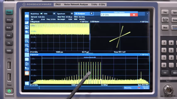
The first step is a look at the signal with a spectrum analyzer, which was not encouraging. Were the unit generating a pure sine wave as it should, we wouldn’t see the forest of spikes indicating harmonics across the band. The oscilloscope isn’t much better; the waveform is closer to a square wave than a sine. Under the hood, he found a PIC microcontroller and a MAX2870 frequency synthesizer, but a conspicuous absence of any RF filtering components, which explains how the output got so crusty. Granted, $200 is not a lot to spend compared to what a lab-grade signal generator with such a wide frequency range would cost. And sure, external filters could help. But for $200, it seems reasonable to expect at least some filtering.

We applaud [electronupdate] for taking one for the team here and providing some valuable tips on RF design dos and don’ts. We’re used to seeing him do teardowns of components, like this peek inside surface-mount inductors, but we like thoughtful reviews like this too.

Continue reading “Fail Of The Week: How Not To Design An RF Signal Generator”