A Look Inside A 70-GHz Electromechanical Attenuator

It might not count as “DC to daylight,” but an electromechanical attenuator that covers up to 70 GHz is pretty close, and getting a guided tour of its insides is quite a treat.

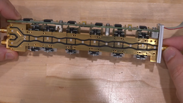
Perhaps unsurprisingly, this one comes to us from [Shahriar] at “The Signal Path,” where high-end gear most of us never get a chance to work with goes for one last hurrah after it releases the magic smoke. And indeed, that appears to be exactly what happened to the Rohde & Schwarz 75 dB step attenuator, a part that may have lived in the front end of one of their spectrum analyzers. As one would expect from such an expensive component, the insides have some pretty special engineering. The signal is carried through the five attenuation stages on a narrow strip of copper. Each stage uses a solenoid to move the strip between either a plain conductor or a small Pi pad with a specified attenuation. The attention to detail inside the cavity is amazing, with great care taken to maintain the physical orientation of the stripline to prevent impedance mismatches and unwanted reflections.

The Pi pads themselves are fascinating, too, especially under [Shahriar]’s super-duper microscope. All of them were destructively removed from the cavity before getting to him, but it’s still pretty clear what’s going on. That’s especially true with the 5-dB pad, which bears clear signs of the overload that brought on the demise of the whole attenuator. We suppose a repair would have been feasible if it had been just the one pad that needed replacement, but with all of them broken, it’s off to the scrap bin. Or to the recycler — there appears to be plenty of gold in there.

We thought this was a fantastic look under the covers of an exquisitely engineered part. Too bad it didn’t rate the [Shahriar] X-ray treatment, as this multimeter repair or this 60-GHz phased array did. Oh, well — maybe next time.

Continue reading “A Look Inside A 70-GHz Electromechanical Attenuator”

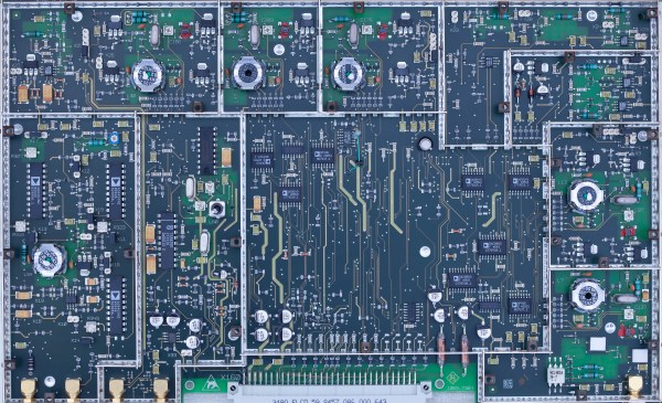
Rohde & Schwarz FSIQ 7 Logic Analyzer's RF module, back side. (Source: Roberto Barrios)

Rohde & Schwarz FSIQ Signal Analyzer IF-Filter Module Repair

Who can’t resist snapping up a piece of really expensive laboratory testing gear for next to nothing when browsing eBay or similar? Maybe it’s giving you mournful eyes when browsing through a yard sale. Often such gear is sold for cheap because it’s defective, but with a bit of attention, can be brought back to life. This is how [Roberto Barrios] ended up with a Rohde & Schwarz FSIQ 7 signal analyzer lounging around his place for a few months until he got it fixed.

See anything wrong with this picture?

Part of the fix was replacing a busted RF converter module (A160 IF-Filter) with a used-but-working replacement, but this left the device with odd calibration failures. In the process of tracing down the cause, [Roberto] took many high-resolution images of both sides of the PCBs in order to reverse-engineer the circuit. To complicate matters, the calibration results indicated that the unit’s filters were fine on boot-up, but would deviate after a few minutes.

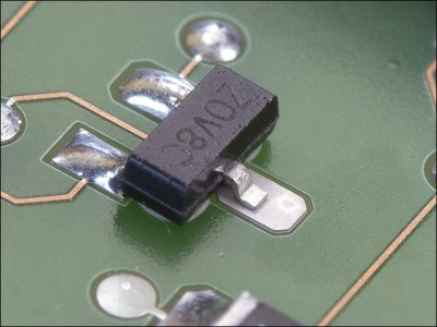
After extending the filter module to work outside the enclosure and experimental use of a hot air gun, ultimately the cause was tracked down to an unsoldered pad. Considering the extremely simple cause of the failure, it would seem that R&S QA had an off-day when that replacement module was produced. If there’s a lesson to be learned here it is probably that a simple visual inspection is sometimes all that is needed to fix a hardware issue.

What are your expensive gear repair stories? What did you learn that could save others hours of their time?

3.2 GHz Vector Signal Generator Tear Down

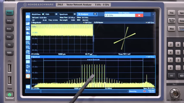
[The Signal Path] snagged a fancy Rohde & Schwarz vector signal generator that can go up to 3.2 GHz, but sadly it wasn’t in working order. It powered up and even put out a 1 GHz signal, but the amplitude output was very wrong. Interestingly relative changes to the output were correct, it was just that the absolute output amplitude was off by quite a bit and changed with frequency. That started a detective job which you can follow along in the video below.

The instrument is pretty high-end, and did not report any problems even during self-check. This implied that all the internals were probably good and whatever was wrong probably lay close to the output. The service manual’s block diagram wasn’t terribly useful, especially given that all the processing portions appear to work well.

Continue reading “3.2 GHz Vector Signal Generator Tear Down”