Whenever a project calls for displaying numbers, a 7-segment display is the classic and straightforward choice. However, if you’re more into a rustic, retro, almost mystical, and steampunky look and feel, it’s hard to beat the warm, orange glow of a Nixie tube. Once doomed as obsolete technology of yesteryear, they have since reclaimed their significance in the hobbyist space, and have become such a frequent and deliberate design choice, that it’s easy to forget that older devices actually used them out of necessity for lack of alternatives. Exhibit A: the impulse counter [soldeerridder] found in the attic that he turned into a general-purpose, I2C controlled display.
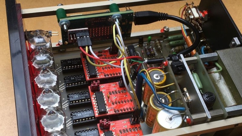
Instead of just salvaging the Nixie tubes, [soldeerridder] kept and re-used the original device, with the goal to embed an Intel Edison module and connect it via I2C. Naturally, as the counter is a standalone device containing mainly just a handful of SN74141 drivers and SN7490 BCD counters, there was no I2C connectivity available out of the box. At the same time, the Edison would anyway replace the 7490s functionality, so the solution is simple yet genius: remove the BCD counter ICs and design a custom PCB containing a PCF8574 GPIO expander as drop-in replacement for them, hence allowing to send arbitrary values to the driver ICs via I2C, while keeping everything else in its original shape.
Containing six Nixie tubes, the obvious choice is of course to use it as a clock, but [soldeerridder] wanted more than that. Okay, it does display the time, along with the date, but also some sensor values and even the likes on his project blog. If you want to experiment with Nixie tubes yourself, but lack a matching device, Arduino has you obviously covered. Although, you might as well go the other direction then.


cool hack. reminds me of the Schneider Venus and Mars multimere combi. one is a 4+ nixie voltmeter and the other the converter for resistors and currents. On the back is a big centronics connector with all the signals to the nixies laid out. quite convenient. the machine uses a cordwood PCB layout and I remember having a hell of a time reverse engineering the thing, as for normal use, there would be a interconnect connector on the centronics, connecting all the signals from and to the nixies. so the voltmeter part is completely separated from the nixies without a jumper connector or another device connected to it on the back.
unfortunately its not on the front of the project queue atm.
This (the modularization of the display, which used to be the hard part) reminds me of a series of project articles Don Lancaster did for Popular Electronics in the late 1960x/early 70s. No, not Nixie, but modules that did BCD counting using RTL chips (!) and displayed on a column of incandescent lamps (because LEDs were expensive and not very bright!). He used these modules to make a frequency counter, a digital voltmeter, a stopwatch, and a couple of other projects. https://www.tinaja.com/glib/ufreqcn1.pdf
Actually … I2C to BCD