There’s a problem with fuses. On the face of it, testing would seem to be a one-shot deal — exceed the rated current and see if it blows. But once you know the answer, the device is useless. If only there were a way to test fuses without damaging them.
As it turns out there is, and [Kerry Wong] weaves quite a tale about his attempts to non-destructively test fuses. The fuses in question are nothing fancy — just the standard glass tube type, from a cheap assortment kit off Amazon. Therein lies the problem: can such cheap devices be trusted? Finding out requires diving much deeper into the technology of fuses than many people will have done, including understanding how the thermal and electrical characteristics of the fuse element behave.
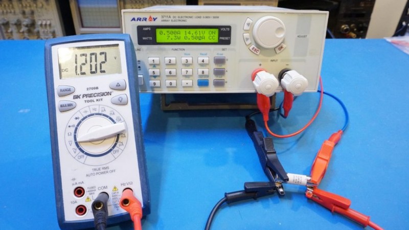
[Kerry]’s test setup is simple, consisting of a constant current power supply and a voltmeter across the fuse to measure the voltage drop caused by the resistance of the fuse element. As he ramps up the current, the voltage drop increases linearly due to the increase in resistance of the alloy with increasing temperature. That only lasts up to a point, where the fuse resistance starts increasing exponentially. Pushing much past the point where the resistance has doubled would blow the fuse, so that’s the endpoint of his tests. Perhaps unsurprisingly, his no-name fuses all went significantly beyond their rated current, proving that you get what you pay for. See the video below for the tests and an analysis of the results.
It’s handy to know there’s a way to check fuses without popping them, and we’ll file this one away for future reference. Don’t forget that you should always check the fuse when troubleshooting, because you never know what the last person did to it.


Did not watch the video but this is a goof up:
(quote) As he ramps up the current, the voltage drop increases linearly due to the increase in resistance (/quote)
Voltage ramps up liniearly because voltage = Current * Resistance. (with a constant resistance). The exponential part starts when the fuse starts heating up and it’s resistance also starts increasing.
Yep, came to say the same thing. Since V=IR, voltage will increase linearly with current without any change in the resistance. If R becomes dependent on I, then the change in V will become non-linear.
Agreed. “Linear” is an appropriate descriptor for an ideal fixed resistor’s I-V curve if it were sitting on an infinite heat sink.
As an aside, something many people may not realize is that usually the fuse element is soldered to the ferrules. It’s obviously not possible to clean the inside after assembly so non-corrosive flux is used. However in theory, if the fuse were operated just right, it’s possible to exceed the melting point of the solder without melting the fuse element. If the solder were to wick along the fuse element it would increase the cross sectional area. That causes lower resistance and greater heat loss through conduction to the ferrules. The designs of fuse elements for some fuses use stamped foil rather than fine wire, and it’s possible also that the solder partially fill the stamped cuts or voids—amplifying the effect.
Point is, running a fuse >100% of its rated continuous value for extended periods can degrade its performance. Fuse performance is only well defined for specific test conditions—usually starting from cold (25C).
Another thing is that most fuses rely on the source supplying enough energy to create an arc and vaporize the fuse element. Problem is, as the arc is formed the resistance increases, increasing the voltage drop across the fuse. At some point the series impedance of the fuse and load will reduce current until the arc is extinguished (and note also that arc time is affected by ac or dc current—ac will often extinguish the arc at zero cross and may not re-form the arc after voltage increases, but dc can sustain an arc until the vaporized element dispersed or the arc is extinguished). The larger the rated voltage, the more likely it is that the fuse will not properly blow with a low voltage source. I have seen 15kV fuses tested with a 600V source, which partially re-connected (kOhm resistance range) after cooling after a melt test. Test them with medium voltage (for those of us more used to power anything below 1000V is “low voltage”) even at low current, and it pops wide open.
Just the incoherent ramblings of an engineer who has devoted way too much thought to fuses.
All fuses have a certain characteristic, begin with quick or slow blow. So a static current test does not give you enough data. You do not get any information about thermal time constants or I²t melting energy. The working of a fuse is a question of power and TIME.
The resistance change over temperature depends on the specific alloy used and the melting point of it is another variable.
Think of a tungsten bulb: It’s resistance increases more then tenfold (10 *) between room temperature and operating temp.
Most (possibly all) fuses will handle more current than their rated value depending on the circumstances. Quality fuses will have a data sheet that documents all of the states it is possible to meet within the specification stated for the fuse. All fuses will reach a point where they will never go open circuit if you hit them with enough voltage and current. Between that and doing nothing there are reams and reams of data about how it behaves. How it behaves as you load it really does not tell you anything about how it behaves as a fuse.
This is why the ones in your Fluke (Probably Bussmann) cost an arm and a leg to replace. :)
Before you pull out the meter, look at the end caps – often, the rating is stamped there, sometimes as part of the type number – “AGC3” will be a 3A type AGC fuse.
Fuses🤔🤔
FYI: https://www.rfcafe.com/references/popular-electronics/images5/fuse-selection-popular-electronics-july-1972-2_small.jpg
First off, fuses blow current are temperature depending, they can age and the usual tolerance. It is not Star Trek where you can count down to exactly when something fails. Their “rating” is actually a point where they don’t blow. If you look at the graph, it is actually above 1X current rating. (~ 1.2X?) It get worse as you are supposed to also derate the fuse in your design.
Then there is the different type of fuses: very fast, fast, and time delay in which the I^2T (time: ~1, ~20, ~300 seconds)
If you are not running the current long enough for the fuse to heat up, you might not be predicting when it blows correctly.
Mr. Wong,
You have a masters degree in electrical engineering. So there is no excuse for the poor quality of the information in this video. It is disappointing to see EEs that refuse to correctly promulgate the applied physics of safety engineering.
Please reference the UL248 series and the IEC60269 series of standards.
You need to focus your discussion on rated breaking (interrupt) current and the respective I2T curves.
respectfully,
Brian
According to his website, Mr. Wong’s degree is in “Electrical and Computer Engineering”. This is NOT the same thing as electrical engineering. My own experience with computer engineers is that their training is mostly in software, so it doesn’t surprise me that he isn’t well versed in electrical testing.
Another fuse gotcha to be aware of: fuse heating (and therefore its tendency to blow) goes as the square of current (I*I*R), and since R is dependent on temperature, it’s actually even higher power than square.
This is important because of the crest factor: If passing DC, where average current equals RMS current, no problem. But if running AC, you may need to overrate the fuse a bit: If that AC is charging capacitors, so high current flows for only part of the cycle (i.e., high crest factor), then the RMS current can be much higher than the average.
In a real-life example, a 12A fuse consistently blows on a rectifier circuit that measures 10A average, but a 15A fuse works fine.
“ his no-name fuses all went significantly beyond their rated current, proving that you get what you pay for”
Or more than you paid for, in this case.
I must object to the comment “you get what you pay for”. It seems to me that the results follow very much the same parameters you would find from a genuine BUSS fuse.
(They are far from precision devices and if your circuit will be damaged by twice the fuse current maybe there is more work to be done)
T
I’d be interested to know what real-life situations big fuses like this actually protect against (and that an RCD or circuit breaker don’t catch first), and how common it is that a 3A fuse on a smaller device saves you but a 13A wouldn’t.
I can’t think I’ve ever seen a mains fuse go. (RCDs plenty of times, but not a fuse). Fuses in dev boards, saved plenty of stuff, but they’re all resettable fuses, not this type.
IMO, I think mains fuses are not to save stuff, but save you.
No, they are supposed to save the mains cable.
They are to keep things from burning / starting on fire, not to protect the circuit.
Circuit breakers on a mains circuit are there to protect the mains cabling not the appliance.
The fuse in the appliance protects the appliance.
NFM: No, even within appliances, the fuse isn’t to protect the appliance; it’s still to protect the wiring and the flammable thinga near the wiring. When an appliance goes overcurrent, the appliance has already failed.
And the winner is…
I read this whole thread to see if anyone got it right and you win.
Other than some special purposes like the Fluke fuse that doubles as a calibrated Current Shunt as well as protection, or output fuses protecting from an errant load, fuses are good at preventing fires. Period. When a supply fuse blows, something is hosed already. (Something I never fail to forget at the closing stages of a project, wasting untold hours researching the best fuse to use.)
That is all UL cares about when you use a fuse.
Yes there are exceptions, I blew 2 variac fuses today and it still works, (but I think it is kind of clunky for the abuse). Here’s the irony of that; I am blowing fuses testing our design for the nextgen GFCI.
My dad used to joke about protecting fuses with transistors, trying to “save” damaged electronics with a fuse is very unreliable.
“You get what you pay for” vs “Price is no guarantee of Quality”. I prefer the latter motto, personally!
Is the testing being carried out going to add to the “ageing” of the fuse, so it will blow at a slightly lower current, than if it hadn’t been tested?
This should be easy to test: If a fuse is tested multiple times (with cool-down periods between tests), then if the test is damaging the fuse, this would result in a lower “trip current” characteristic as the cumulative test cycles increases.
Maybe send a short really high frequency pulse through them, using the skin effect to blast off the surface layer of the fuse wire, trimming them back into spec? Perhaps grounding a band on the glass to gather up the vapour deposition.
Hey, that’s a pretty neat idea. Now we just need a >1 GHz, >10 MW source that I can pulse in sub-microsecond pulses. You’d need a few joules. Maybe a big Blumlein pulse generator could do it if you can impedance-match the fuse “load”.
I don’t think high frequency is necessary – if you heat the wire to the point where relatively rapid oxidation occurs, the oxidation should start at the surface anyway. You know, where the oxygen is. But yes, fuses could be “trimmed” by repeatedly heating them. This isn’t far from laser trimming in principle.
Had to make and test some 250 kA fuses once. Large expanded stainless mesh things encased in drain pipe and filled with sand to prevent arc over. Made really bad fulgurites and lots of missing stainless. Good times.
As an an ET(not the alien type) , a dead unit needs the fuse(s) checked first. Visually the fuse may look fine, but I’ve ran into several where the fuse wire simply broke at the end, maybe from vibration.
Well for all you headbangers, Kix wrote a great song “Blow My Fuse”
Mechanical fuses will never be perfect. They are generally rated for a range of voltages and you can not have the same amount of power through the fuse over a range of voltages. On their side, they generally have low resistance so they have a minimal voltage drop and ideally a more consistent amount of power across them as the circuit voltage changes. The good news is most of the time, fuses exist to melt before something we don’t want to burst into flames bursts into flames and there are foruulas from the 1800’s by W. H. Preece in the 1880’s, and I. M. Onderdonk that define this. If you want precisiopn, there are active devics that can either limit current or cut off current at a given threshold. Almost any lab power supply has the ability to current limit. Some have the ability to switch off on overcurrent, and these valuses can be set very precisley. In general fuses are very goosd at doing what they have been designed to do, but given their simple nature, some expermentation may be necessary in picking the correct fuse for an application. A great case in point is in speaker protection fuses.
https://youtu.be/lJKcdlj-Uiw
Errors in the video:
1: Fuses are not rated for interrupt current, but for continuous pass current, i.e., the current that can be passed continuously for a long period of time, without blowing the fuse or changing its characteristics.
2: This is supposed to be non-destructive testing, but he allows the fuse to glow red hot for a considerable amount of time. Since the fuse element is in AIR, this is destructive, as the wire is oxidizing, burning off material, increasing its resistance.
3: He does not repeat the test on any given fuse, to determine whether the test has altered the fuse’s characteristics.
4: He states that the lowest current tests on the .1 A fuse may be inaccurate due to contact resistance. This should not be the case, since he SHOULD be doing this using four-wire sensing, with the voltmeter leads connected to the fuse inboard of the current leads, so that there is zero current in the voltage sensing circuit. From the video I can see that he has the voltmeter connected to the current-carrying alligator clips. This is bad practice, because yes, indeed, the measured voltage WILL be higher due to contact resistance. Easily prevented, but nothing done.
5: In testing the .1A fuse at 100 mA, he says “at this point I think the current may actually be over 100 mA”. Huh? Where would the additional current be coming from? If he doesn’t trust the current setting of the power supply, he should be using a separate meter to measure the current, rather than making wild-ass guesses. If he has reason to distrust the current the power supply says it is supplying, but does nothing to either confirm or refute this suspicion, then the whole test is invalid.
And THEN, Dan Maloney goes on to throw his own error into the mix, saying “his no-name fuses all went significantly beyond their rated current, proving that you get what you pay for”, even though there was no control case, and even though the sample size for these no-name fuses was TWO. Also, there was no apples-to-apples testing of 3AG type glass fuses from “reputable” sources. Looking at a few datasheets from Littelfuse, it is pretty clear that 3AG type fuses should be expected open at no more than about double the rated current, but unless you actually do the same test, you don’t really know, do you?
With this being a fairly novel approach to fuse testing, there was really no excuse for NOT testing trusted-brand devices as a control.
Fuses are an interesting subject. They seem so simple on the surface, but when you dig in, the subject becomes fiendishly complex. I