Everything is a fuse if you run enough current through it. Or at least [JohnsonFarms.us] seems to think so, which has led him to design 3D-printed fuses made from conductive PLA filament.
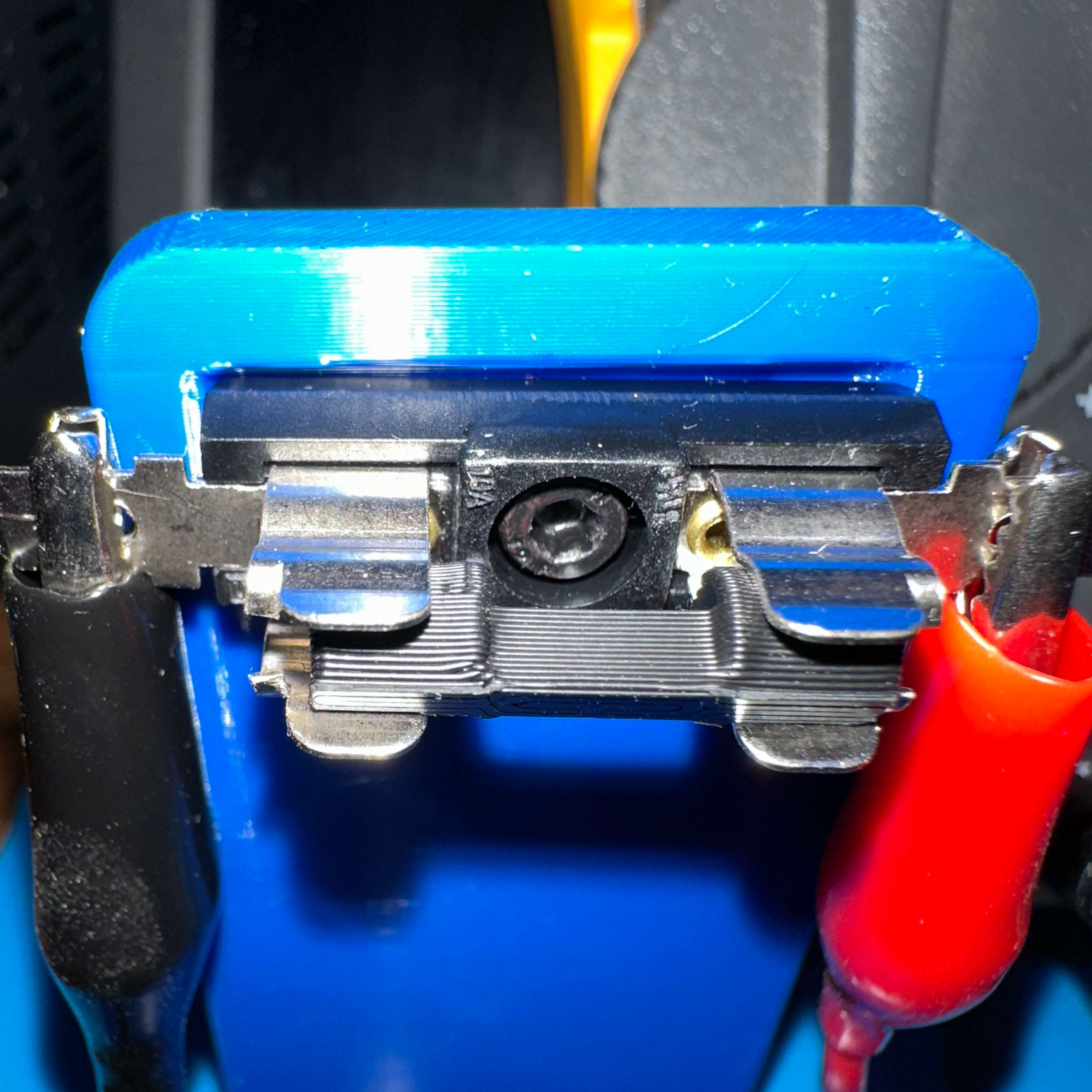
In theory a 3D printed fuse works the same as a normal one: excessive current draw will cause the conductive plastic to briefly become a heater, causing it to self-destruct and break the electrical connection. There’s a risk of melted plastic and perhaps a nonzero combustion risk, but [JohnsonFarms.us] is less interested in whether this is a good idea and more interested in whether it can work at all, and with what degree of predictability and/or regret.
His experiments so far show that printed fuses are essentially meltable resistors with values between 300 Ω and 1250 Ω, depending on shape. What it takes to bring those to roughly 60 °C, where PLA softens, and around 150 °C, where PLA melts, is next on the to-do list.
Whatever conclusions are reached, it is interesting to think of conductive filament as a meltable resistor, and ponder what unusual applications that might allow.
Most conductive filaments have high resistance, but not all. Some, like Electrifi by Multi3D, have extremely low resistance and were used in a project that made 3d-printed logic gates.