When it comes to understanding computers, sometimes it’s best to get a good understanding of the basics. How is data stored? How does the machine process this information? In order to answer these questions a bit more and start learning programming, [Nakazoto] built a 10-bit binary adder with relays.
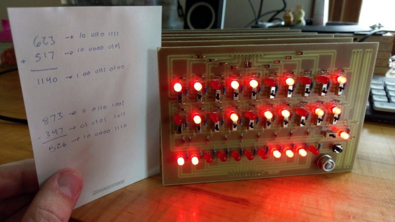
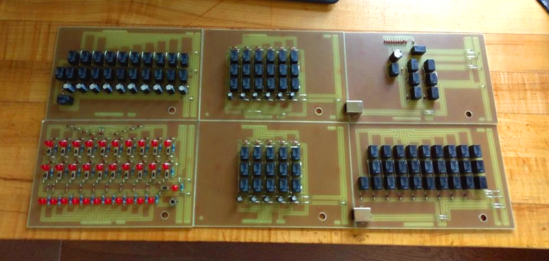
The build is designed from the ground up, including the PCBs, which are milled using a CNC machine. There are six boards: the input board, sequencer board, 2 sum register boards, a carry register board and a 1-bit ALU board. The input board has 32 LEDs on it along with the switches to turn on each bit on or off. In total, 96 relays are used and you can hear them clacking on and off in the videos on the page. Finally, there is a separate switch that sets the adder into subtraction mode.
Usually, [Nakazoto]’s website is mostly about cars, but this is a nice diversion. The article has a lot of detail about both the design and build as well as the theory behind the adder. Other articles on binary adders on the site include this one which uses bigger relays, and this 2-bit adder which uses 555 timers.


Pretty cool! Front panel looks messed up though, would push the LEDs to the right and right-align them (same as relays), then use top-left space (above carry LED) for switches etc.
If you check the link, make sure you play that 5000 relay video with CC and Auto translate set to English…
Thanks!
The front panel is designed as it is simply because that’s the only way I could get the traces to fit. Since the mill isn’t really designed for things this small, I have to run a fairly fat trace width (1.0mm). Also, I don’t really have a jig, so double sided boards are a near impossibility as any slight misalignment would destroy the board when it came time to drill holes. The result is an almost cathartic battle against space and organization, that sometimes yields less than ideal configurations just to fit everything on one board.
Thanks for the explanation!
It’s easy to comment, this project sure as hell beats the shit out of anything I’ve done with relays. And I just love how it works, I played that video from “so if I push this little black button here …” more times than I care to admit :)
No problem!
The sound is pretty much the entire reason I made it, haha.
Ha! The auto translate is pretty funny. I kind of like the left-align myself, though. this thing is really cool. I want a PCB mill.
Thanks!
Our mill is actually not even remotely designed for PCBs. It has a max Spindle seed of about 3,200 RPM, which I run it at 2,900 RPM, and it lacks the precision of the good desktop ones, which have spindle speeds of around 10,000 RPM. The upshot is I can do really large pieces. I milled a backplane for my next project the other day that was 270mm x 300mm. The Y-axis has 275mm of total travel, so I was pushing it, but it worked surprisingly well.
The desktop ones can be had for a couple hundred dollars and, honestly, it’s so much fun going from idea, to design, to prototype board in an afternoon that I would highly recommend picking one up!
Thanks for showing my post!
As a fair warning, I should have hosted my videos on Youtube as I’m about to smash through my bandwidth limit this month, haha. Fortunately, the month is almost over, so if you guys can’t see the post or videos, try again on the 1st!
Well done!
It’s amazing what people can do with the harder constraints today.
The old relay computers had modular relays that had a wide range if configuration.
Today’s relays are basically all the same with at best two changeovers
The back in the day relays were more diverse.
You could have three contact banks of up to 8 contacts each.
So any combination of make, break, make before break changeover or break before make changeover.
So you could have two changeovers and a make in one bank for example.
Also you could adjust the relays speed, slow operate. Slow release by putting a copper slug on the former or increasing the air gap of the armature or a diode across the coil.
Oh yeah, back when relays ruled the day, there were all sorts of different types. We have a 1963 Williams Merry Widow pinball machine and the entire thing is built from contacts and solenoids. It’s really interesting seeing the versatility and functionality they were able to get with such relatively simple components.
Now, I did have a few options for different relays, but the main reason I used SPDT relays is because the little Omron G5V1 relays I’m using are absolutely tiny, which helped keep the overall size of the project down. Also, I can be a little slow on the uptake sometimes and using just one type of relay helped me wrap my head around the complex logic required, haha.
@nakazoto would you be open to sharing the board vector files? I’ve been looking at your project for a while now and wouldn’t mind recreating it.
cheers
Just saw this adder on Veritasium and would like to build one for my students. Any chance in sharing the schematics? Or pcb layout?
Hello, I would like to build this myself but the link seems to be broken. Is there any way for me to get the schematics??
Looks like Usagi Motors went offline — I updated the link to use the Wayback Machine (thanks, Internet Archive!). Should work now.
This is a nice device. I am interested in building it. Can someone give me the schematics of the boards?