If you’re at all familiar with digital computing, you’ll know that computers represent everything in binary values of one and zero. Except that’s not technically the only way to do computing! You can use any numerical system you like if you build your hardware to suit, as [Jeroen Brinkman’s] ternary adder demonstrates.
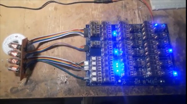
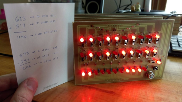
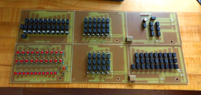
As you might guess from the prefix, “ternary” refers to a base-3 numerical system. In this case, [Jeroen] implemented a balanced ternary system, which effectively uses values of -, 0, and + instead of just 1 and 0. The adder is built using relay logic, and is designed to handle 4 trits—the ternary equivalent of bits, where each trit can have one of the three aforementioned states. On a hardware level, trit states are represented with voltages of -5, 0, or 5 V in this case, and are handled with special tri-state switching elements that [Jeroen] constructed out of simple SPDT relays.
[Jeroen]’s write-up does a great job of explaining both ternary basics as well as the functioning of the adder. It’s also quite intuitive because it’s possible to see the relays clicking away and the LEDs flashing on and off as the circuit does its work to add values stored in ternary format.
If you’re trying to get your head around ternary computing from the very lowest level, this project is a great place to start. We’ve seen base 3 hardware built before, too—like this simple ternary computer lashed together from accessible components.
If you’re cooking up your own computing apparatus that uses some weird number system or something, remember—we’d love to hear about it on the tipsline!