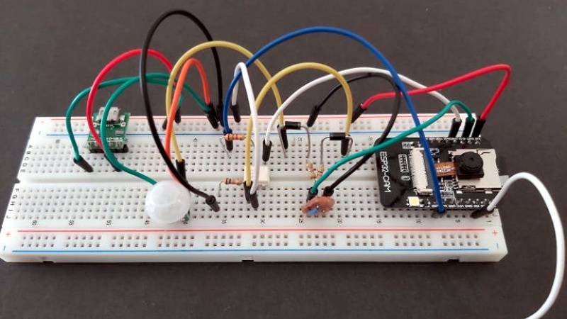
There’s no shortage of things to like about the ESP8266 and ESP32, but if we had to make a list of the best features these WiFi-enabled microcontrollers have to offer, their power management capabilities would certainly be near the top. Which is how we assumed [Mark] was able to take a whopping 23,475 pictures on his ESP32 camera while powered by nothing more exotic than four AA batteries from the grocery store.
 But as it turns out, the full story is quite a bit more interesting. As far as we can tell, [Mark] isn’t bothering with the ESP32’s sleep modes all. In fact, it looks like you could pull this trick off with whatever chip you wanted, which certainly makes it worth mentally filing away for the future; even if it depends on a fairly specific use case.
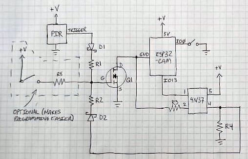
In the most simplistic of terms, [Mark] is cutting power to the ESP32 completely when it’s not actively taking pictures. The clever circuit he’s come up with only turns on the microcontroller when a PIR sensor detects something moving around in front of the camera. Once the chip is powered up and running code, it brings one of its GPIO pins high which in turn triggers a 4N37 optoisolator connected to the gate on the circuit’s MOSFET. As long as the pin remains high, the circuit won’t cut power to the ESP32. This gives the chip time to take the requested number of pictures and get everything in order before bringing the pin low and allowing the circuit to pull the plug.
If you’re looking to maximize runtime without wrangling any MOSFETs, we’ve seen some excellent examples of how the low power modes on the ESP8266 and ESP32 can be put to impressive use.
[Thanks to Jason for the tip.]


That is very neat the only trouble I see is the length of time between detection and taking a photo, I didn’t time it but it seems to be around 1sec which unfortunately a bit too long. I use a number of trail cams for security purposes and find the 0.3secs they claim is often too long.
That’s not to say this is a great implementation.
Oops that didn’t come out right –
This is a great implementation and really good price
I look forward to a great implementation of the commenting system here on hackaday
Thanks! There’s definitely a gap between the initial trigger and when the pictures are taken. The ESP32 is the first MCU I’ve worked with that loads its own OS. :-)
That, and The Engineer’s Mini Notebook style… yummy :)
I still have a copy of “Getting Started In Electronics” in the basement. Well, most of it, anyway – it saw a lot of use back in the early 80s… I’ve always liked the way Forrest Mims drew stuff up.
I have that exact same board, and over 100 slightly used AA’s. The batteries would die of old age before running out! I wonder if there’s a way to use an RTC circuit to trigger an hourly wake up instead?
On ESP8266, gpio15 for wakeup.
do not launch wifi to gain autonomy, when you need WiFi, use the parameters of the last connection to reduce the power consumption by 50%
Yep, some have a programmable output!
The ESP32 has an ultra low power processor that you can run on while the main processors are shut down. With 100 AA batteries, you could probably run that thing for years. :-D
There’s nothing pulling the gate low, so it may or may not latch on some times, when the weather is right.
yeah, but that’s how you catch a ghost
– Whenever I see a circuit using opto without actually requiring isolation, it tells me that the person have no idea how to do proper level shifting.
– IO0 can be grounded while Q1 is not enabled leading to current conducting through ESD diode at IO0
– R4 can be moved to gate of Q1 and R1, R2 and R5 can be eliminated. Q1 is a MOSFET, so it doesn’t require a base resistor to limit current as in the case of a bipolar transistor.
– use a large value for R4. It just need to be large enough to counter the leakage current of the schottky.
– In the case of IO0, either tie the ground side of the switch to GND pin of ESP32 or at least put a resistor in series to the IO0 pin.
Good point about the resistors – simpler is better, for sure!
Despite the very few available pins on the ESP32-CAM, I try to stay away from using IO0 for anything other than setting the ESP to programming mode – hence the switch.
As for the 4N37, I’m not level shifting with it. It’s tied to the GND pin of the ESP (not GND of the whole board) because when the ESP first starts up the pins are in an uncertain state and the signal from the ESP needs to stay off until it boots and takes control of IO13 properly. If the 4N37 is tied to the board ground, it makes the cct (through IO13, ouch) and the ESP gets stuck in a never-boot loop.
And, like I said in my post, there are better ways to do it but it’s what I had on hand at the time.
You can use a pass transistor for level shifting. (in Cascode commonly used for level shifting)
P-MOSET: Source to IO13, gate to GND on ESP and drain as output.
PNP:E to IO13, B with a series resistor to GND on ESP and C as output.
BTW the pass transistor would only turn on when the ESP have power, so it does what your opto is doing. You just don’t know that a level shifter would solve the problem.
Heh… in my post I actually said “When building this, I was limited to what I had on hand – a P-channel MOSFET might be a better choice”.
But that’s cool – I appreciate you sharing your knowledge!
The existence of the ESD diodes is something that is not taught in school. That is something that comes with experience.
I did question myself the need for an opto-coupler
Omg, so smart! Your hackaday projects must be full with all that knowledge.
Much better than your empty comments.
Hmm… good point. I haven’t had any problems with it yet but it’s probably just a matter of time. Thanks for pointing that out, I appreciate it!
The whole system behavior may depend on how fast it takes for the gate charge to leak out – without a pulldown it takes a while. You may even want to add extra capacitance there to control how long it takes to turn off, so you can power down your MCU cleanly before it browns out.
It can sometimes lead to weird issues like flash corruption, because the CPU executes random commands as it shuts down – which is why it should have the BOD circuitry enabled that shuts it down cleanly when it detects the power supply going down.
Yes, a pulldown resistor is advisable.
So, the PIR sensor gives you a long enough pulse to reliably hold the ESP32 on long enough for the firmware to latch on with the 4N37?
btw the opto-coupler is not a terrible thing; it works, and low parts-count!
Hey!
Thanks for posting my project, this is pretty cool! I was trying to figure out why I suddenly had a whole bunch of comments on my blog. :-)
If you’re interested in circuits like this, then also check out the ubiquitous transistor tester with atmega328 and LCD. It uses BJT’s instead of MOSfets because of lower leakage. I could not really measure leakage current as it’s below my measuring thresshold of a few hundred nA (At room temperature).
The rest of the power circuit in that tester was a really bad example.
Maybe a camera-enabled bootloader is in order… (take the photo, then let the OS load to triage it)
What a beautiful clear diagram on the graph paper! Thank you!
Thanks! I go through a lot of graph paper. :-)
Wouldn’t a thyristor do a similar job?
It’s not trivial to turn the thyristor off once you get it started, because you have to drive the current to zero or even in reverse before it closes.
That and more voltage drops than MOSFET for low current circuits.
average AA battery’s capacity being 1473 mWh (Great AA Alkaline Battery Test – Pt 3 by lui_gough) means the approximate energy for each 1600*1200 photo saved was 250 microWatt-hours